Network Positioning System
·
Quick Start Guide
14
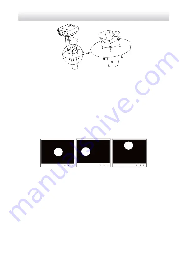
Figure 2-2
Fix the Positioning System (Type IV)
Note:
The thickness of the pedestal steel plate should be more than 5 mm.
2)
Connect the corresponding cables.
2.
Adjust the laser.
1)
Observe the location of laser spot in the image. Adjust the zoom ratio of the lens
to a large value, the laser supplementary lighting system will adjust the light
according to the zoom ratio, and then you can see the laser spot on the live view
image.
If the spot location is the same as shown in figure A, you can skip the step of
adjusting the laser; if not, you need to adjust the laser.
A
B
C
Figure 2-3
Laser Spot Location
Note:
You can zoom in/out to adjust the size of the laser spot. The spot location shown in
figure A is the optimum location.
2)
For type III camera, loosen the inner hexagon screws with the wrench and open
the lid of housing.
Содержание DY5 Series
Страница 1: ...Network Positioning System Quick Start Guide...
Страница 34: ...UD10187B...


