


DS-TD10M-1 Multi-Target Speed-Measuring Radar User Debugging Manual
12
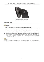
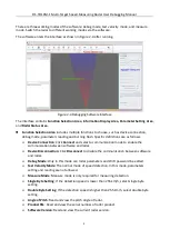
Figure 2-6
Device Connection Settings
4.
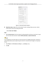
(Optional) You can also select the connection method as WIFI connection. The computer must
have been connected to the radar via WiFi in advance. Click OK and the device will connect
automatically.
During the device connection process, the software will automatically read the software
version, device number and current setting parameters. These parameters will be displayed in
the Radar Status Area at the bottom of the interface.
The name of radar is defined as RAD + 11-digit serial No., and the original password is RADAR2019.
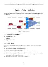
2.4.2 Debug Radar
After road information (number of lanes and lane width) and installation parameters (trigger
distance and installation height) are set, view the real-time vehicle status displaying window to
check whether the vehicle is in the corresponding lane or not. Set the angle correction and
horizontal shift as required to ensure that the target vehicle is in the corresponding lane.
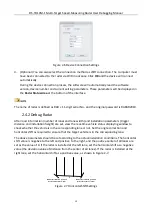
The above parameters should be set according to the actual installation conditions. The horizontal
shift value is negative to the left and positive to the right, and the positive center of all lanes are
set as the value of 0. If the radar is installed at the left lane, set the horizontal shift as a negative
value (the deviation value of distance from the center of all lanes). If the radar is installed at the
right lane, set the horizontal shift as a positive value, as shown in Figure 2-7.
0
Radar installation position
Horizontal shift -3.8m
Radar installation position
Horizontal shift +3.8m
Figure 2-7
Horizontal Shift Settings