background image

User Manual of Network Video Recorder   

72 

2)


Choose the camera you want to configure. 

3)


Select the check box after the 

Enable Schedule

 item. 

4)


Click 

Edit 

button or click on the color icon under the edit button and draw the schedule line on the panel. 

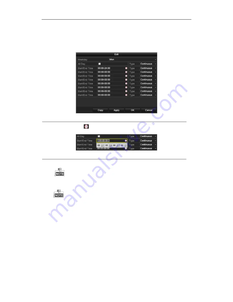
Edit the schedule: 

I.


In the message box, you can choose the day to which you want to set schedule.


Figure 5. 8


Recording Schedule Interface 


You can click the 

  button to set the accurate time of the schedule. 

II.


To schedule an all-day recording, check the checkbox after the 

All Day

 item. 


Figure 5. 9


Edit Schedule 


III.


To arrange other schedule, set the Start/End time for each period. 


Up to 8 periods can be configured for each day. And the time periods can’t be overlapped each other. 

IV.


Select the record type in the dropdown list. 


To  enable  Motion,  Alarm,  M  |  A  (motion  or  alarm),  M  &  A  (motion  and  alarm)  and  VCA  (Video 

Content Analysis) triggered recording and capture, you must configure the motion detection settings, 

alarm  input  settings  or  VCA  settings  as  well.  For  detailed  information,  refer  to 

Chapter  8.1

  and 

Chapter 9


The VCA settings are only available to the smart IP cameras. 

Repeat the above edit schedule steps to schedule recording or capture for other days in the week. If the 

schedule can also be applied to other days, click

 Copy

.


Содержание DS-96NI-ST

Страница 1: ...Network Video Recorder User Manual UD 6L0202D2116A01...

Страница 2: ...mentioned below are the properties of their respective owners Legal Disclaimer TO THE MAXIMUM EXTENT PERMITTED BY APPLICABLE LAW THE PRODUCT DESCRIBED WITH ITS HARDWARE SOFTWARE AND FIRMWARE IS PROVID...

Страница 3: ...rference that may cause undesired operation EU Conformity Statement This product and if applicable the supplied accessories too are marked with CE and comply therefore with the applicable harmonized E...

Страница 4: ...safety regulations of the nation and region Please refer to technical specifications for detailed information Input voltage should meet both the SELV Safety Extra Low Voltage and the Limited Power Sou...

Страница 5: ...s properly secured to a rack or shelf Major shocks or jolts to the unit as a result of dropping it may cause damage to the sensitive electronics within the unit Use the device in conjunction with an U...

Страница 6: ...rence only This manual is applicable to the models listed in the following table Series Model DS 9600NI I8 DS 9608NI I8 DS 9616NI I8 DS 9632NI I8 DS 9664NI I8 DS 7600NI I2 DS 7608NI I2 DS 7616NI I2 DS...

Страница 7: ...ual switch and auto switch are provided and the auto switch interval is configurable Quick setting menu is provided for live view Motion detection video tampering video exception alert and video loss...

Страница 8: ...nd maintenance of backup devices Either Normal or Hot Spare working mode is configurable to constitute an N 1 hot spare system Alarm and Exception Configurable arming time of alarm input output Alarm...

Страница 9: ...NVIF Remote search playback download locking and unlocking of the record files and support downloading files broken transfer resume Remote parameters setup remote import export of device parameters Re...

Страница 10: ...omized Protocols 40 2 5 4 Editing IP Cameras Connected to the PoE Interfaces 43 Chapter 3 Live View 46 3 1 Introduction of Live View 47 3 2 Operations in Live View Mode 48 3 2 1 Front Panel Operation...

Страница 11: ...back by Smart Playback 97 6 1 6 Playing Back by System Logs 99 6 1 7 Playing Back External File 101 6 1 8 Playing Back by Sub periods 102 6 1 9 Playing Back Pictures 102 6 2 Auxiliary Functions of Pla...

Страница 12: ...9 16 Defocus Detection 146 9 17 PIR Alarm 146 Chapter 10 VCA Search 147 10 1 Face Search 148 10 2 Behavior Search 150 10 3 Plate Search 151 10 4 People Counting 152 10 5 Heat Map 153 Chapter 11 Netwo...

Страница 13: ...uota Mode 198 13 6 Configuring Disk Clone 200 13 7 Checking HDD Status 202 13 8 HDD Detection 204 13 9 Configuring HDD Error Alarms 206 Chapter 14 Camera Settings 207 14 1 Configuring OSD Settings 208...

Страница 14: ...ix 231 17 1 Specifications 232 DS 9600NI I8 232 DS 7600NI I2 233 DS 7600NI I2 P 234 DS 7700NI I4 235 DS 7700NI I4 P 236 17 2 Glossary 237 17 3 Troubleshooting 238 17 4 Summary of Changes 244 17 5 List...

Страница 15: ...User Manual of Network Video Recorder 14 Chapter 1 Introduction...

Страница 16: ...when an event is detected Turns off when the device is unarmed The arm disarm status can be changed by pressing and holding on the ESC button for more than 3 seconds in live view mode 2 IR Receiver Re...

Страница 17: ...sed in a list field Turns on off PTZ light if applicable in PTZ control mode Switches between play and reverse play in playback mode F2 AUX Cycles through tab pages Switches between channels in synchr...

Страница 18: ...ent of the PTZ camera in PTZ control mode 10 POWER ON OFF Long press the button for more than 3 seconds to turn on off the NVR DS 7600NI I2 P Figure 1 2 DS 7600NI I2 Series Table 1 2 Description of Fr...

Страница 19: ...sequence The Enter button is used to confirm selection in menu mode or used to check checkbox fields and ON OFF switch 3 DIRECTION In menu mode the direction buttons are used to navigate between diff...

Страница 20: ...n of the Soft Keyboard Icons No Name Description 1 POWER Power on off the device 2 DEV Enables Disables Remote Control 3 Alphanumeric Buttons Same as Alphanumeric buttons on front panel 4 EDIT Button...

Страница 21: ...If there is no response after you press any button on the remote follow the procedure below to troubleshoot Steps 1 Go to Menu Settings General More Settings by operating the front control panel or th...

Страница 22: ...vider The operation of the mouse Table 1 5 Description of the Mouse Control Name Action Description Left Click Single Click Live view Select channel and show the quick set menu Menu Select and enter D...

Страница 23: ...board 1 Figure 1 6 Soft Keyboard 2 Description of the buttons on the soft keyboard Table 1 6 Description of the Soft Keyboard Icons Icon Description Icon Description Number English letter Lowercase Up...

Страница 24: ...B 3 0 interface Universal Serial Bus USB ports for additional devices such as USB mouse and USB Hard Disk Drive HDD 7 RS 232 Interface Connector for RS 232 devices 8 eSATA Connects external SATA HDD C...

Страница 25: ...4 HDMI Interface HDMI video output connector 5 ALARM IN Connector for alarm input ALARM OUT Connector for alarm output 6 LAN Network Interface 1 10 100 1000 Mbps self adaptive Ethernet interface 7 USB...

Страница 26: ...erface Universal Serial Bus USB ports for additional devices such as USB mouse and USB Hard Disk Drive HDD 6 RS 232 Interface Connector for RS 232 devices 7 VGA DB9 connector for VGA output Display lo...

Страница 27: ...User Manual of Network Video Recorder 26 Chapter 2 Getting Started...

Страница 28: ...After startup the Power indicator LED remains blue A splash screen with the status of the HDD appears on the monitor The row of icons at the bottom of the screen shows the HDD status X means that the...

Страница 29: ...recommend you create a strong password of your own choosing using a minimum of 8 characters including upper case letters lower case letters numbers and special characters in order to increase the secu...

Страница 30: ...ant settings of the NVR If you don t want to use the Setup Wizard at that moment click the Cancel button You can also choose to use the Setup Wizard next time by leaving the Start wizard when the devi...

Страница 31: ...000M network interface for DS 7600NI I2 P and DS 7700NI I4 P 4 Click Next button after you configured the basic network parameters Then you will enter the EZVIZ Cloud P2P interface Configure the EZVIZ...

Страница 32: ...rk Parameters 6 Click Next button after you configured the network parameters which takes you to the RAID configuration window The RAID is supported by DS 9600NI I8 series NVR only Figure 2 9 Array Ma...

Страница 33: ...HDD 10 Click Next button You enter the Adding IP Camera interface 11 Click Search to search the online IP Camera and the Security status shows whether it is active or inactive Before adding the camera...

Страница 34: ...of Network Video Recorder 33 Figure 2 12 Search for IP Cameras 12 Click Next button Configure the recording for the added IP Cameras Figure 2 13 Record Settings 13 Click OK to complete the startup Se...

Страница 35: ...14 Login Interface 2 Input Password 3 Click OK to log in In the Login dialog box if you enter the wrong password 7 times the current user account will be locked for 60 seconds Figure 2 15 User Accoun...

Страница 36: ...of Network Video Recorder 35 Figure 2 16 Logout 2 Click Logout After you have logged out the system menu operation on the screen is invalid It is required to input a user name and password to unlock...

Страница 37: ...terface For the IP camera detected online in the same network segment the Security status shows whether it is active or inactive Figure 2 17 IP Camera Management Interface 2 Click the inactive icon of...

Страница 38: ...monthly or weekly can better protect your product 4 Click OK to finish the acitavting of the IP camera And the security status of camera will be changed to Active 2 5 2 Adding the Online IP Cameras P...

Страница 39: ...extfiled and then click the Add button to add it OPTION 2 Steps 1 Select the Add IP Camera option from the right click menu in live view mode or click Menu Camera Camera to enter the IP camera managem...

Страница 40: ...channels Figure 2 22 Selecting Multiple Channels OPTION 3 Steps 1 On the IP Camera Management interface click the Custom Adding button to pop up the Add IP Camera Custom interface Figure 2 23 Custom A...

Страница 41: ...amera The camera is disconnected you can click the icon to get the exception information of camera Delete the IP camera Play the live video of the connected camera Advanced settings of the camera Upgr...

Страница 42: ...choose the channel to connect by selecting the channel port No in the dropdown list 2 Click OK to save the settings and exit the editing interface To edit advanced parameters 1 Drag the horizontal scr...

Страница 43: ...P camera interface to enter the protocol management interface Figure 2 28 Protocol Management Interface There are 16 customized protocols provided in the system you can edit the protocol name and choo...

Страница 44: ...list please refer to Figure 2 29 Figure 2 29 Protocol Setting 3 Choose the protocols you just added to validate the connection of the network camera 2 5 4 Editing IP Cameras Connected to the PoE Inter...

Страница 45: ...thod in the drop down list Plug and Play It means that the camera is connected to the PoE interface so in this case the parameters of the camera can t be edited The IP address of the camera can only b...

Страница 46: ...User Manual of Network Video Recorder 45 Input the IP address the user name and password of administrator manually and click OK to add the IP camera Figure 2 32 Edit IP Camera Interface Manual...

Страница 47: ...User Manual of Network Video Recorder 46 Chapter 3 Live View...

Страница 48: ...ht of the screen for each channel showing the status of the record and alarm in the channel so that you can know whether the channel is recorded or whether there are alarms occur as soon as possible T...

Страница 49: ...MI VGA for DS 7600NI I2 and DS 7700NI I4 DS 9600NI I8 When the HDMI1 HDMI2 VGA1 and VGA2 are all connected the HDMI1 VGA1 is used as main output and the HDMI2 VGA2 is used as the aux output DS 7600NI...

Страница 50: ...channels Add IP Camera Enter the IP Camera Management interface and manage the cameras Playback Enter the playback interface and start playing back the video of the selected channel immediately PTZ E...

Страница 51: ...iew mode of the main output monitor the menu operation is not available while Aux output mode is enabled 3 2 4 Quick Setting Toolbar in Live View Mode On the screen of each channel there is a quick se...

Страница 52: ...e image parameters like brightness contrast saturation and hue according to the actual demand Figure 3 4 Image Settings Customize Live View Strategy can be selected to set strategy including Real time...

Страница 53: ...th the specified size detected in the front of the camera the device will capture the human face and save in HDD Move the mouse onto the icon to show the real time stream information including the fra...

Страница 54: ...tput to configure the settings for The DS 9600NI I8 provides VGA HDMI and VGA2 HDMI2 and DS 7600NI I2 P and DS 7700NI I4 P provide the HDMI and VGA video outputs Live View Mode Designates the display...

Страница 55: ...on different models 2 Select the small window and double click on the channel number to display the channel on the window You can click button to start live view for all the channels and click to sto...

Страница 56: ...e image quality channel zero encoding is supported as an option for you Steps 1 Enter the Live View Settings interface Menu Configuration Live View 2 Select the Channel Zero Encoding tab Figure 3 9 Li...

Страница 57: ...User Manual of Network Video Recorder 56 Chapter 4 PTZ Controls...

Страница 58: ...the PTZ camera Steps 1 Enter the PTZ Settings interface Menu Camera PTZ Figure 4 1 PTZ Settings 2 Click the PTZ Settings button to set the PTZ parameters Figure 4 2 PTZ General 3 Choose the camera fo...

Страница 59: ...e the directional button to wheel the camera to the location where you want to set preset and the zoom and focus operations can be recorded in the preset as well 3 Enter the preset No 1 255 in the pre...

Страница 60: ...show the general settings of the PTZ control Figure 4 4 PTZ Panel General 4 Click to enter the preset No in the corresponding text field 5 Click the Call Preset button to call it 4 2 3 Customizing Pa...

Страница 61: ...button to add the next key point to the patrol or you can click the OK button to save the key point to the patrol You can delete all the key points by clicking the Clear button for the selected patro...

Страница 62: ...rt button and click corresponding buttons in the control panel to move the PTZ camera and click the Stop button to stop it The movement of the PTZ is recorded as the pattern 4 2 6 Calling Patterns Pur...

Страница 63: ...r Scan can be enabled to trigger the scan in the horizantal direction in the predefined range This function is supported by some certain models Steps 1 Enter the PTZ Control interface Menu Camera PTZ...

Страница 64: ...ton on the front panel or click the PTZ Control icon in the quick setting bar to enter the PTZ setting menu in live view mode 2 Click the button to show the one touch function of the PTZ control Figur...

Страница 65: ...re are 3 one touch park types selectable click the corresponding button to activate the park action Park Quick Patrol The dome starts patrol from the predefined preset 1 to preset 32 in order after th...

Страница 66: ...e In PTZ control mode the PTZ panel will be displayed when a mouse is connected with the device If no mouse is connected the icon appears in the lower left corner of the window indicating that this ca...

Страница 67: ...User Manual of Network Video Recorder 66 Chapter 5 Recording and Capture Settings...

Страница 68: ...and initialize it Menu HDD General Figure 5 1 HDD General 2 Check the storage mode of the HDD 1 Click Advanced to check the storage mode of the HDD 2 If the HDD mode is Quota please set the maximum re...

Страница 69: ...end are not configurable Enabling it helps to ensure the high video quality with a lowered bitrate The H 265 and H 264 should be supported by the connected IP camera 2 Click the More Settings button t...

Страница 70: ...stream are selectable for recording When you select sub stream you can record for a longer time with the same storage space 3 Click Apply to save the settings You can enable the ANR Automatic Network...

Страница 71: ...ecorder 70 Figure 5 6 Capture Parameters 2 Configure the parameters 3 Click Apply to save the settings The interval is the time period between two capturing actions You can configure all the parameter...

Страница 72: ...to choose the Capture tab in the Schedule interface Steps 1 Enter the Record Schedule interface Menu Record Capture Schedule 2 Configure Record Schedule 1 Select Record Capture Schedule Figure 5 7 Re...

Страница 73: ...5 9 Edit Schedule III To arrange other schedule set the Start End time for each period Up to 8 periods can be configured for each day And the time periods can t be overlapped each other IV Select the...

Страница 74: ...interface to save the settings Draw the schedule I Click on the color icons you can choose the schedule type as continuous or event Figure 5 11 Draw the Schedule II Click the Apply button to validate...

Страница 75: ...User Manual of Network Video Recorder 74 Figure 5 12 Copy Schedule to Other Channels...

Страница 76: ...nce center and so on In this chapter you can follow the steps to schedule a record which triggered by the detected motion Steps 1 Enter the Motion Detection interface Menu Camera Motion Figure 5 13 Mo...

Страница 77: ...t the motion detection event to trigger recording 6 Click Apply to save the settings 7 Click OK to back to the upper level menu 8 Exit the Motion Detection menu 3 Edit the Motion Detection Record Sche...

Страница 78: ...ed recording or capture Steps 1 Enter the Alarm setting interface Menu Configuration Alarm Figure 5 16 Alarm Settings 2 Click Alarm Input Figure 5 17 Alarm Settings Alarm Input 1 Select Alarm Input nu...

Страница 79: ...e upper level menu Repeat the above steps to configure other alarm input parameters If the settings can also be applied to other alarm inputs click Copy and choose the alarm input number Figure 5 19 C...

Страница 80: ...ss the REC SHOT button on the front panel Figure 5 20 Manual Record 2 Enable the Manual Recording 1 Select Record on the left bar 2 Click the status button before camera number to change to 3 Disable...

Страница 81: ...User Manual of Network Video Recorder 80 Green icon means that the channel is configured the capture schedule After rebooting all the continuous capture will be canceled...

Страница 82: ...e the record or capture schedule on holiday for that year You may want to have different plan for recording and capture on holiday Steps 1 Enter the Record setting interface Menu Record Holiday Figure...

Страница 83: ...e are three different modes for the date format to configure holiday schedule 4 Set the start and end date 5 Click Apply to save settings 6 Click OK to exit the Edit interface 3 Enter Record Capture S...

Страница 84: ...DD and click to enter the Local HDD Settings interface 1 Set the HDD property to Redundancy Figure 5 25 HDD General Editing 2 Click Apply to save the settings 3 Click OK to back to the upper level men...

Страница 85: ...5 26 Record Parameters 3 Select Camera you want to configure in the drop down list 4 Check the checkbox of Redundant Record Capture 5 Click OK to save settings and back to the upper level menu Repeat...

Страница 86: ...enu 4 Click to enter editing interface 5 Configuring HDD group 1 Choose a group number for the HDD group 2 Click Apply and then in the pop up message box click Yes to save your settings 3 Click OK to...

Страница 87: ...erface Menu Playback 2 Check the checkbox of channel s in the channel list and then double click to select a date on the calendar Figure 5 29 Normal Playback 3 During playback click the button to lock...

Страница 88: ...it to to unlock the file and the file is not protected Lock File when Export Steps 1 Enter Export setting interface Menu Export Figure 5 31 Export 2 Select the channels you want to search by checking...

Страница 89: ...change it to to unlock the file and the file is not protected Figure 5 33 Unlocking Attention 5 9 2 Setting HDD Property to Read only Steps 1 Enter HDD setting interface Menu HDD Figure 5 34 HDD Gener...

Страница 90: ...the HDD change the property to R W If there is only one HDD and is set to Read only the NVR can t record any files Only live view mode is available If you set the HDD to Read only when the NVR is sav...

Страница 91: ...User Manual of Network Video Recorder 90 Chapter 6 Playback...

Страница 92: ...teps Choose a channel in live view mode and click the button in the quick setting toolbar In the instant playback mode only record files recorded during the last five minutes on this channel will be p...

Страница 93: ...back video files recorded in specified time duration Multi channel simultaneous playback and channel switch are supported Steps 1 Enter playback interface Menu Playback 2 Check the checkbox of channe...

Страница 94: ...nnels Figure 6 5 Toolbar of Playback The indicates the start end time of the record Playback progress bar use the mouse to click any point of the progress bar or drag the progress bar to locate specif...

Страница 95: ...ime line The playing speed of 256X is supported 6 1 3 Playing Back by Event Search Purpose Play back record files on one or several channels searched out by event type e g alarm input motion detection...

Страница 96: ...ar in the bottom part of Playback interface can be used to control playing process Figure 6 7 Interface of Playback by Event You can click or button to select the previous or next event Please refer t...

Страница 97: ...ment Click button to enter the File Management interface and click Tag to manage the tags You can check edit and delete tag s Figure 6 9 Tag Management Interface Playing back by Tag Steps 1 Select the...

Страница 98: ...mark it with green color and play it in the normal speed while the video without motion will be played in the 16 time speed The smart playback rules and areas are configurable Before you start To get...

Страница 99: ...tion Draw quadrilateral for the intrusion detection Draw rectangle for the intrusion detection Set full screen for motion detection Clear all Start Stop clipping File management for video clips Stop p...

Страница 100: ...o at Set the speed to play the non related video Max 8 4 1 are selectable Play Related Video at Set the speed to play the related video Max 8 4 1 are selectable Pre play and post play is not available...

Страница 101: ...ayback by System Logs Set search time and type and click Search button Figure 6 15 System Log Search Interface 3 Choose a log with record file and click button to enter Playback interface If there is...

Страница 102: ...llowing steps to look up and play back files in the external devices Steps 1 Enter Tag Search interface Menu Playback 2 Select the External File in the drop down list on the top left side The files ar...

Страница 103: ...e dropdown list Up to 16 screens are configurable Figure 6 19 Interface of Sub periods Playback According to the defined number of split screens the video files on the selected date can be divided int...

Страница 104: ...ce Up to 4000 pictures can be displayed each time 5 Choose a picture you want to view and click button You can click Back to return to the search interface Figure 6 20 Result of Picture Playback 6 The...

Страница 105: ...click button until the speed changes to Single frame and one click on the playback screen represents reverse playback of one frame It is also feasible to use button in toolbar Using the Front Panel Cl...

Страница 106: ...click Export All or Export to export the clips pictures files tags to local storage device 6 2 4 Reverse Playback of Multi channel Purpose You can play back record files of multi channel reversely Up...

Страница 107: ...Playback Interface The record files will be marked by two lines on the process bar The upper one indicates the record files of the selected channel and the lower one indicates the record files of all...

Страница 108: ...User Manual of Network Video Recorder 107 Chapter 7 Backup...

Страница 109: ...ck Export button The time duration of record files on a specified channel cannot exceed one day Otherwise the message box Max 24 hours are allowed for quick export will pop up Figure 7 1 Quick Export...

Страница 110: ...interface until all record files are exported Figure 7 3 Export Finished 4 Check backup result Choose the record file in Export interface and click button to check it The Player player exe will be exp...

Страница 111: ...t interface Menu Export Normal Picture 2 Select the cameras to search 3 Set search condition and click Search button to enter the search result interface The matched video files or pictures are displa...

Страница 112: ...ant to back up and click Export button to enter Export interface If the inserted USB device is not recognized Click the Refresh button Reconnect device Check for compatibility from vendor You can also...

Страница 113: ...s USB flash drives USB HDDs USB writer SATA writer or eSATA HDD Quick Backup and Normal Backup are supported Steps 1 Enter Export interface Menu Export Event 2 Select the cameras to search 3 Select th...

Страница 114: ...r captured pictures in playback mode to export directly during Playback using USB devices USB flash drives USB HDDs USB writer SATA writer or eSATA HDD Steps 1 Enter Playback interface Please refer to...

Страница 115: ...erface Figure 7 12 Storage Device Management 2 Backup device management Click New Folder button if you want to create a new folder in the backup device Select a record file or folder in the backup dev...

Страница 116: ...working device Set a hot spare device Add a hot spare device on normal device Add the normal device on the hot spare device Start Finish Figure 7 13 Building Hot Spare System 7 3 1 Setting Hot Spare D...

Страница 117: ...are device Figure 7 15 Setting Working Mode for Working device 5 Click the Apply button to save the settings 7 3 3 Managing Hot Spare System Steps 1 Enter the Hot Spare Settings interface of the hot s...

Страница 118: ...spare device will record the video of the IP Camera connected to the working device for backup and the working status of the hot spare device is displayed as Backing up The record backing up can be fu...

Страница 119: ...User Manual of Network Video Recorder 118 Figure 7 19 Synchronizing...

Страница 120: ...User Manual of Network Video Recorder 119 Chapter 8 Alarm Settings...

Страница 121: ...itivity Click button and set alarm response actions 3 Click Trigger Channel tab and select one or more channels which will start to record capture or become full screen monitoring when motion alarm is...

Страница 122: ...5 Click Handling tab to set up alarm response actions of motion alarm please refer to Chapter Setting Alarm Response Actions 6 If you want to set motion detection for another channel repeat the above...

Страница 123: ...Alarm Status Interface of System Configuration 2 Set up the handling action of the selected alarm input Check the Enable checkbox and click Settings button to set up its alarm response actions Figure...

Страница 124: ...of the alarm input please refer to Chapter Setting Alarm Response Actions 6 If necessary select PTZ Linking tab and set PTZ linkage of the alarm input Set PTZ linking parameters and click OK to comple...

Страница 125: ...User Manual of Network Video Recorder 124 to copy the settings to them Figure 8 8 Copy Settings of Alarm Input...

Страница 126: ...ckbox of Enable Video Loss Alarm and click button to set up handling action of video loss 3 Set up arming schedule of the handling actions 1 Select Arming Schedule tab to set the channel s arming sche...

Страница 127: ...User Manual of Network Video Recorder 126 5 Click the OK button to complete the video loss settings of the channel...

Страница 128: ...ndling action of the channel Check the checkbox of Enable Video Tampering Detection Drag the sensitivity bar to set a proper sensitivity level Use the mouse to draw an area you want to detect video ta...

Страница 129: ...t Arming Schedule of Video Tampering 4 Select Linkage Action tab to set up alarm response actions of video tampering alarm please refer to Chapter Setting Alarm Response Actions 5 Click the OK button...

Страница 130: ...cable IP Conflicted Duplicated IP address Illegal Login Incorrect user ID or password Record Capture Exception No space for saving recorded files or captured images Hot Spare Exception Disconnected wi...

Страница 131: ...tions 2 Check the checkbox of Enable Event Hint Figure 8 14 Event Hint Settings Interface 3 Click the to set the type of event to be displayed on the image Figure 8 15 Event Hint Settings Interface 4...

Страница 132: ...on Email Linkage Send an email with alarm information to a user or users when an alarm is detected Please refer to Chapter 11 2 8 Configuring Email for details of Email configuration Trigger Alarm Out...

Страница 133: ...steps to set up arming schedule of other days of a week You can also use Copy button to copy an arming schedule to other days Click the OK button to complete the video tampering settings of the alarm...

Страница 134: ...alarm can be cleared only by clicking Clear button in the following interface Steps Select the alarm output you want to trigger or clear and make related operations Menu Manual Alarm Click Trigger Cl...

Страница 135: ...User Manual of Network Video Recorder 134 Chapter 9 VCA Alarm...

Страница 136: ...terface first All VCA detection must be supported by the connected IP camera Please refer to the User Manual of Network Camera for the detailed instructions for the all VCA detection types 9 1 Face Re...

Страница 137: ...face detection rules You can click and drag the slider to set the detection sensitivity Sensitivity Range 1 5 The higher the value is the more easily the face can be detected Figure 9 3 Set Face Dete...

Страница 138: ...Vehicle Detection 5 Click to configure the trigger channel arming schedule and linkage actions for the Blacklist Whitelist and Others 6 Click the Rule Settings to enter the rule settings interface Co...

Страница 139: ...nkage actions for the line crossing detection alarm 6 Click the Rule Settings button to set the line crossing detection rules 1 Select the direction to A B A B or A B A B Only the arrow on the B side...

Страница 140: ...User Manual of Network Video Recorder 139 Up to 4 rules can be configured Figure 9 7 Draw Line for Line Crossing Detection 8 Click Apply to activate the settings...

Страница 141: ...ct loitering in the region When the duration of the object in the defined detection area is longer than the set time the alarm will be triggered 2 Click and drag the slider to set the detection sensit...

Страница 142: ...User Manual of Network Video Recorder 141 Up to 4 rules can be configured Figure 9 9 Draw Area for Intrusion Detection 8 Click Apply to save the settings...

Страница 143: ...ance Detection 4 Check the Enable checkbox to enable this function 5 Click to configure the trigger channel arming schedule and linkage actions for the line crossing detection alarm 6 Click the Rule S...

Страница 144: ...in the region If you set the value as 5 alarm is triggered after the object loitering in the region for 5s and if you set the value as 0 alarm is triggered immediately after the object entering the r...

Страница 145: ...ion for 10s Up to 4 rules can be configured 9 12 Unattended Baggage Detection Purpose Unattended baggage detection function detects the objects left over in the pre defined region such as the baggage...

Страница 146: ...x of Save VCA Picture to save the captured pictures of VCA detection 3 Select the VCA detection type to Audio Exception Detection 4 Click to configure the trigger channel arming schedule and linkage a...

Страница 147: ...ase refer to the Chapter 9 2 Face Detection for operating steps to configure the defocus detection The Sensitivity in the Rule Settings ranges from 1 to 100 and the higher the value is the more easily...

Страница 148: ...User Manual of Network Video Recorder 147 Chapter 10 VCA Search...

Страница 149: ...he picture and play the picture related video file according to the specified conditions Before you start Please refer to Chapter 9 2 Face Detection for configuring the face detection Steps 1 Enter th...

Страница 150: ...picture item and click to play it You can also click to stop the playing or click to play the previous next file 6 If you want to export the captured face pictures to local storage device connect the...

Страница 151: ...ehavior search 3 Specify the start time and end time for searching the matched pictures Figure 10 4 Behavior Search Interface 4 Select the VCA detection type from the dropdown list including the line...

Страница 152: ...captured pictures to local storage device connect the storage device to the device and click Export All to enter the Export interface Click Export to export all pictures to the storage device 10 3 Pl...

Страница 153: ...of Section 10 1 Face Search for the operation of the search results 10 4 People Counting Purpose The People Counting is used to calculate the number of people entered or left a certain configured area...

Страница 154: ...The heat map function is usually used to analyze the visit times and dwell time of customers in a configured area The heat map function must be supported by the connected IP camera and the correspond...

Страница 155: ...and start heat map statistics and the results are displayed in graphics marked in different colors As shown in the figure above red color block 255 0 0 indicates the most welcome area and blue color...

Страница 156: ...User Manual of Network Video Recorder 155 Chapter 11 Network Settings...

Страница 157: ...and DS 7700NI I4 and two working modes are configurable multi address network fault tolerance etc One self adaptive 10M 100M 1000M network interface is provided for DS 7600NI I2 P and DS 7700NI I4 P F...

Страница 158: ...ds use the same IP address and you can select the Main NIC to LAN1 or LAN2 By this way in case of one NIC card failure the device will automatically enable the other standby NIC card so as to ensure t...

Страница 159: ...d after reboot You can go to Menu Maintenance System Info Network interface to view the status of PPPoE connection Please refer to Chapter Viewing System Information for PPPoE status 11 2 2Configuring...

Страница 160: ...on the EZVIZ official website www ezviz7 com 11 2 3Configuring DDNS Purpose If your NVR is set to use PPPoE as its default network connection you may set Dynamic DNS DDNS to be used for network access...

Страница 161: ...obtained from the PeanutHull website Figure 11 7 PeanutHull Settings Interface NO IP Enter the account information in the corresponding fields Refer to the DynDNS settings 1 Enter Server Address for N...

Страница 162: ...on the server You can register the alias of the device domain name in the HiDDNS server first and then enter the alias to the Device Domain Name in the NVR you can also enter the domain name directly...

Страница 163: ...the device on the HiDDNS server you can access your device via web browser or Client Software with the Device Domain Device Name OPTION 1 Access the Device via Web Browser Open a web browser and ente...

Страница 164: ...e password of the device Figure 11 13 Access Device via iVMS4200 12 Click the Apply button to save and exit the interface 11 2 4Configuring NTP Server Purpose A Network Time Protocol NTP Server can be...

Страница 165: ...protocol to get device status and parameters related information Steps 1 Enter the Network Settings interface Menu Configuration Network 2 Select the SNMP tab to enter the SNMP Settings interface as...

Страница 166: ...ast address spans the Class D IP range of 224 0 0 0 to 239 255 255 255 It is recommended to use the IP address ranging from 239 252 0 0 to 239 255 255 255 When adding a device to the CMS Client Manage...

Страница 167: ...n web browser input the IP address of device and the web server will select the language automatically according to the system language and maximize the web browser 2 Input the correct user name and p...

Страница 168: ...an be configured to send an Email notification to all designated users if an alarm event is detected etc an alarm or motion event is detected or the administrator password is changed Before configurin...

Страница 169: ...ender Select Receivers Select the receiver Up to 3 receivers can be configured Receiver The name of user to be notified Receiver s Address The Email address of user to be notified Enable Attached Pict...

Страница 170: ...the same network segment as that of the LAN IP address of the router Steps 1 Enter the Network Settings interface Menu Configuration Network 2 Select the NAT tab to enter the port mapping interface F...

Страница 171: ...the value of the port No for each device should be unique Figure 11 26 External Port Settings Dialog Box 3 Click Apply button to save the settings 4 You can click Refresh button to get the latest stat...

Страница 172: ...al port value and other required contents Each item should be corresponding with the device port including server port http port RTSP port and https port Figure 11 29 Setting Virtual Server Item The a...

Страница 173: ...Virtual Host Purpose You can directly get access to the IP camera management interface after enabling this function The Virtual host function can be only configured through the web browser Steps 1 Ent...

Страница 174: ...urpose You can check the network traffic to obtain real time information of NVR such as linking status MTU sending receiving rate etc Steps 1 Enter the Network Traffic interface Menu Maintenance Net D...

Страница 175: ...eld of Destination Address 4 Click Test button to start testing network delay and packet loss The testing result pops up on the window If the testing is failed the error message box will pop up as wel...

Страница 176: ...incorrect Figure 11 37 Export Network Packet 4 Click Export button to start exporting 5 After the exporting is complete click OK to finish the packet export as shown in Figure 11 38 Figure 11 38 Pack...

Страница 177: ...If the message box pops out with other information instead of this one you can click Network button to show the quick setting interface of the network parameters 11 4 4Checking Network Statistics Purp...

Страница 178: ...Figure 11 41 Network Stat Interface 3 Check the bandwidth of IP Camera bandwidth of Remote Live View bandwidth of Remote Playback bandwidth of Net Receive Idle and bandwidth of Net Send Idle 4 You ca...

Страница 179: ...User Manual of Network Video Recorder 178 Chapter 12 RAID...

Страница 180: ...ay which is realized by the software and RAID0 RAID1 RAID5 and RAID 10 are supported You can enable the RAID function on your demand Before you start Please install the HDD s properly and it is recomm...

Страница 181: ...D Advanced Figure 12 2 Enable RAID Interface 2 Check the checkbox of Enable RAID 3 Click the Apply button to save the settings 12 1 2One touch Configuration Purpose Through one touch configuration you...

Страница 182: ...on to start configuring array If you install 4 HDDs or above for one touch configuration a hot spare disk will be set by default It is recommended to set hot spare disk for automatically rebuilding th...

Страница 183: ...Array Purpose You can manually create the array of RAID 0 RAID 1 RAID 5 and RAID 10 In this section we take RAID 5 as an example to describe the manual configuration of array and virtual disk Steps 1...

Страница 184: ...RAID 1 2 HDDs need to be configured for RAID 1 If you choose RAID 5 at least 3 HDDs must be installed If you choose RAID 10 the number of HDDs installed should be even in the range of 4 16 4 Click OK...

Страница 185: ...sk is in Degraded status you can restore it to Functional by array rebuilding Before you start Please make sure the hot spare disk is configured 1 Enter the Physical Disk Settings interface to configu...

Страница 186: ...igured then you can rebuild the array manually to restore the array when the virtual disk is in Degraded status Steps 1 Enter the Array Settings interface The disk 3 is lost Menu HDD RAID Array Figure...

Страница 187: ...l of Network Video Recorder 186 start rebuilding 5 You can enter the Array Settings interface to view the rebuilding status 6 After rebuilding successfully the array and virtual disk will restore to F...

Страница 188: ...isk Steps 1 Enter the Array Settings interface Menu HDD RAID Array Figure 12 15 Array Settings Interface 2 Select an array and click to delete the array Figure 12 16 Confirm Array Deletion 3 In the po...

Страница 189: ...pgrade the firmware by local backup device or remote FTP server Steps 1 Enter the Firmware interface to check the information of the firmware including the version maximum physical disk quantity maxim...

Страница 190: ...User Manual of Network Video Recorder 189 Chapter 13 HDD Management...

Страница 191: ...ized HDD Figure 13 1 Message Box of Uninitialized HDD Click Yes button to initialize it immediately or you can perform the following steps to initialize the HDD Steps 1 Enter the HDD Information inter...

Страница 192: ...Network Video Recorder 191 5 After the HDD has been initialized the status of the HDD will change from Uninitialized to Normal Figure 13 5 HDD Status Changes to Normal Initializing the HDD will erase...

Страница 193: ...utton to enter the Add NetHDD interface as shown in Figure 13 7 Figure 13 7 HDD Information Interface 3 Add the allocated NetHDD 4 Select the type to NAS or IP SAN 5 Configure the NAS or IP SAN settin...

Страница 194: ...rom the list shown below 4 Click the OK button to add the selected IP SAN disk Up to 1 IP SAN disk can be added Figure 13 9 Add IP SAN Disk 6 After having successfully added the NAS or IP SAN disk ret...

Страница 195: ...to Backup using eSATA HDDs in Chapter Backing up by Normal Video Picture Search for operating instructions Record Capture use the eSATA for record capture Refer to the following steps for operating in...

Страница 196: ...rage Mode 2 Set the Mode to Group as shown in Figure 13 13 Figure 13 13 Storage Mode Interface 3 Click the Apply button and the following Attention box will pop up Figure 13 14 Attention for Reboot 4...

Страница 197: ...set to read only to prevent important recorded files from being overwritten when the HDD becomes full in overwrite recording mode When the HDD property is set to redundancy the video can be recorded...

Страница 198: ...User Manual of Network Video Recorder 197 At least 2 hard disks must be installed on your NVR when you want to set a HDD to Redundancy and there is one HDD with R W property...

Страница 199: ...e NVR must be rebooted to enable the changes to take effect Figure 13 18 Storage Mode Settings Interface 3 Select a camera for which you want to configure quota 4 Enter the storage capacity in the tex...

Страница 200: ...me quota settings You can also click the checkbox of IP Camera to select all cameras 7 Click the OK button to finish the Copy settings and back to the Storage Mode interface 8 Click the Apply button t...

Страница 201: ...be connected to the device Steps 1 Enter the HDD Advanced Setting interface Menu HDD Advanced 2 Click the Disk Clone tab to enter the disk clone configuring interface Figure 13 21 Disk Clone Configura...

Страница 202: ...Recorder 201 5 Click the Clone button and a message box pops up Figure 13 23 Message Box for Disk Clone 6 Click the Yes button to continue You can check the clone progress in the HDD status Figure 13...

Страница 203: ...ach HDD which is displayed on the list as shown in Figure 13 25 Figure 13 25 View HDD Status 1 If the status of HDD is Normal or Sleeping it works normally If the status is Uninitialized or Abnormal p...

Страница 204: ...User Manual of Network Video Recorder 203 Figure 13 26 View HDD Status 2...

Страница 205: ...T information list as shown in Figure 13 27 Figure 13 27 S M A R T Settings Interface The related information of the S M A R T is shown on the interface You can choose the self test types as Short Tes...

Страница 206: ...er Manual of Network Video Recorder 205 Figure 13 28 Bad Sector Detection And you can click Error info button to see the detailed damage information And you can also pause resume or cancel the detecti...

Страница 207: ...rom the dropdown list 3 Click the checkbox s below to select the HDD error alarm type s as shown in Figure 13 29 The alarm type can be selected to Audible Warning Notify Surveillance Center Send Email...

Страница 208: ...User Manual of Network Video Recorder 207 Chapter 14 Camera Settings...

Страница 209: ...nu Camera OSD 2 Select the camera to configure OSD settings 3 Edit the Camera Name in the text field 4 Configure the Display Name Display Date and Display Week by clicking the checkbox 5 Select the Da...

Страница 210: ...cy mask 3 Click the checkbox of Enable Privacy Mask to enable this feature Figure 14 2 Privacy Mask Settings Interface 4 Use the mouse to draw a zone on the window The zones will be marked with differ...

Страница 211: ...Parameters Steps 1 Enter the Image Settings interface Menu Camera Image Figure 14 4 Image Settings Interface 2 Select the camera to set image parameters 3 You can click on the arrow to change the valu...

Страница 212: ...User Manual of Network Video Recorder 211 Chapter 15 NVR Management and Maintenance...

Страница 213: ...Menu Maintenance System Info 2 You can click the Device Info Camera Record Alarm Network and HDD tabs to view the system information of the device XXXXXXXXXXX XXXXXXXXXXXXXXXXX XXXXXXXXXXX Figure 15...

Страница 214: ...can be viewed and exported at any time Steps 1 Enter the Log Search interface Menu Maintenance Log Information Figure 15 2 Log Search Interface 2 Set the log search conditions to refine your search in...

Страница 215: ...as shown in Figure 15 4 And you can also click the button to view the related video files if available Figure 15 4 Log Details 6 If you want to export the log files click the Export button to enter th...

Страница 216: ...ormation of added IP camera can be generated into an excel file and exported to the local device for backup including the IP address manage port password of admin etc And the exported file can be edit...

Страница 217: ...arameters Steps 1 Enter the Import Export Configuration File interface Menu Maintenance Import Export Figure 15 6 Import Export Config File 2 Click the Export button to export configuration files to t...

Страница 218: ...grade tab to enter the local upgrade menu as shown in Figure 15 7 Figure 15 7 Local Upgrade Interface 4 Select the update file from the backup device 5 Click the Upgrade button to start upgrading 6 Af...

Страница 219: ...enter the local upgrade interface as shown in Figure 15 8 Figure 15 8 FTP Upgrade Interface 3 Enter the FTP Server Address in the text field 4 Click the Upgrade button to start upgrading 5 After the u...

Страница 220: ...all parameters except the network including IP address subnet mask gateway MTU NIC working mode default route server port etc and user account parameters to the factory default settings Factory Defaul...

Страница 221: ...User Manual of Network Video Recorder 220 Chapter 16 Others...

Страница 222: ...rTerminal The serial port parameters must be the same as the NVR s when connecting with the PC serial port Transparent Channel Connect a serial device directly to the NVR The serial device will be con...

Страница 223: ...standard VGA output resolution mouse pointer speed through the Menu Configuration General interface Steps 1 Enter the General Settings interface Menu Configuration General 2 Select the General tab Fig...

Страница 224: ...the VGA HDMI output For the DS 7600NI I2 P and DS 7700NI I4 P series NVR you can configure the VGA resolution and HDMI resolution respectively And up to 4K 3840 2160 resolution is selectable for the...

Страница 225: ...ter the General Settings interface Menu Configuration General 2 Choose DST Settings tab Figure 16 4 DST Settings Interface You can check the checkbox before the Auto DST Adjustment item Or you can man...

Страница 226: ...ill exit from the current operation menu to live view screen after 5 minutes of menu inactivity Enable HDMI VGA Simultaneous Output for DS 9600NI I8 only By default the video outputs from HDMI and VGA...

Страница 227: ...ce for the first time The Administrator has the permission to add and delete user and configure user parameters 16 5 1Adding a User Steps 1 Enter the User Management interface Menu Configuration User...

Страница 228: ...vel has permission of Two way Audio in Remote Configuration and all operating permission in Camera Configuration by default Guest The Guest user has no permission of Two way Audio in Remote Configurat...

Страница 229: ...nd the NVR Remote Alarm Control Remotely arming notify alarm and exception message to the remote client and controlling the alarm output Remote Advanced Operation Remotely operating HDD management ini...

Страница 230: ...16 11 Figure 16 11 Edit User Interface 4 Edit the corresponding parameters Operator and Guest You can edit the user information including user name password permission level and MAC address Check the...

Страница 231: ...rs and special characters in order to increase the security of your product And we recommend you reset your password regularly especially in the high security system resetting the password monthly or...

Страница 232: ...User Manual of Network Video Recorder 231 Chapter 17 Appendix...

Страница 233: ...1280 720 60Hz 1024 768 60Hz VGA2 HDMI2 output resolution 1920 1080p 60Hz 1280 1024 60Hz 1280 720 60Hz 1024 768 60Hz Audio output 2 ch RCA 2 0Vp p 1 K Decoding Decoding format H 265 H 264 MPEG4 Live vi...

Страница 234: ...20 60Hz 1024 768 60Hz Audio output 1 ch RCA Linear 1 K Decoding Decoding format H 265 H 264 MPEG4 Live view Playback resolution 12 MP 8 MP 6 MP 5 MP 4 MP 3MP 1080p UXGA 720p VGA 4CIF DCIF 2CIF CIF QCI...

Страница 235: ...back resolution 12 MP 8 MP 6 MP 5 MP 4 MP 3 MP 1080p UXGA 720p VGA 4CIF DCIF 2CIF CIF QCIF Synchronous playback 8 ch 16 ch 16 ch Capability 2 ch 4K or 8 ch 1080p 4 ch 4K or 16 ch 1080p 4 ch 4K or 16 c...

Страница 236: ...RCA Linear 1 K Decoding Decoding format H 265 H 264 MPEG4 Live view Playback resolution 12 MP 8 MP 6 MP 5 MP 4 MP 3 MP 1080p UXGA 720p VGA 4CIF DCIF 2CIF CIF QCIF Synchronous playback 8 ch 16 ch 16 c...

Страница 237: ...5 MP 4 MP 3 MP 1080p UXGA 720p VGA 4CIF DCIF 2CIF CIF QCIF Synchronous playback 8 ch 16 ch 16 ch Capability 2 ch 4K or 8 ch 1080p 4 ch 4K or 16 ch 1080p 4 ch 4K or 16 ch 1080p Hard disk SATA 4 SATA in...

Страница 238: ...DNS is a method protocol or network service that provides the capability for a networked device such as a router or computer system using the Internet Protocol Suite to notify a domain name server to...

Страница 239: ...further process There is an audible warning sound Di Di Di DiDi after a new bought NVR starts up Possible Reasons a No HDD is installed in the device b The installed HDD has not been initialized c The...

Страница 240: ...If it is solved finish the process If not please contact the engineer from Hikvision to do the further process The IP camera frequently goes online and offline and the status of it displays as Discon...

Страница 241: ...o output interface in the drop down list and configure the window you want to view The view settings can only be configured by the local operation of NVR Different camera orders and window division mo...

Страница 242: ...ultaneously press Ctrl and C to exit the ping command 2 Verify the network between NVR and PC is connected 1 Open the cmd window in the Start menu or you can press windows R shortcut key to open it 2...

Страница 243: ...lti channel Possible Reasons a Poor network between NVR and IP camera and there exists packet loss during the transmission b The frame rate is not the real time frame rate c The NVR supports up to 16...

Страница 244: ...General and verify the Device Time is correct 2 Verify the search condition is correct Select Playback and verify the channel and time are correct 3 Verify the HDD status is normal Select Menu HDD Gen...

Страница 245: ...7 4 Summary of Changes Version 3 3 4 Added 1 Add the new models of DS 7600NI I2 P and DS 7700NI I4 P 2 Add the support of EZVIZ Cloud P2P Step 4 in Chapter 2 3 Using the Wizard for Basic Configuration...

Страница 246: ...CD2632F I V5 3 0 build150327 2048 1536 DS 2CD2632F IS V5 3 0 build150327 2048 1536 DS 2CD2710F I V5 3 0 build150327 1920 1080 DS 2CD2720F I V5 3 0 build150327 1920 1080 DS 2CD4010F V5 3 0 build150327...

Страница 247: ...721 1280 960 DS 2CD852MF E V2 0 build 110614 1600 1200 V2 0 build 110426 V2 0 build 100521 DS 2CD855F E V5 2 0 build 140721 1920 1080 DS 2CD862MF E V2 0 build 110614 1280 960 V2 0 build 110426 V2 0 bu...

Страница 248: ...1600 1200 iDS 2CD9361 V4 0 0 build150213 2752 2208 iDS 2CD9022 V4 0 0 build150213 1920 1080 iDS 2CD9025 V3 8 2 build141114 1920 1080 iDS 2CD9022 SZ V4 0 0 build150213 1920 1080 DS 2CD9125 KS V3 8 1 bu...

Страница 249: ...V5 2 8 build150124 1280 960 DS 2DF5274 A D A3 D3 AF A3F V5 2 8 build150124 1280 960 iDS 2DF5274 A D A3 D3 AF A3F V5 2 8 build150124 1280 960 DS 2DM5274 A A3 V5 2 8 build150124 1280 960 DS 2DF7276 A D...

Страница 250: ...A D A3 D3 AF A3F V5 2 8 build150124 1920 1080 DS_2DF7230I5 AW V5 2 8 build150124 1920 1080 DS 2AF7220 A D V5 2 8 build150124 1920 1080 DS 2AF7230 A D V5 2 8 build150124 1920 1080 DS 2AF5220 A D V5 2 8...

Страница 251: ...0 build150128 1280 720 DS 2DE4172 A V5 2 10 build150128 1280 720 DS 2DE7194 A A3 V5 2 10 build150128 2048 1536 DS 2DE5194 A A3 V5 2 10 build150128 2048 1536 DS 2DF1 518 V3 2 0 build131223 704 576 DS 2...

Страница 252: ...080 DS 2ZCN3007 B V5 2 7 build141107 1920 1080 DS 2ZMN2007 V5 2 7 build141107 1920 1080 DS 2ZMN3007 V5 2 7 build141107 1920 1080 DS 2ZMN3007 B V5 2 7 build141107 1920 1080 DS 2ZMN0407 V5 2 7 build1411...

Страница 253: ...4301 10D X 00083 A1D 310 V4 12 09 AC 1208 1024 TCM5311 11D X 00023 A1D 310 V4 12 09 AC 1208 960 Arecont AV1305 M 65175 1208 1024 AV2815 65220 1920 1080 AV3105M 65175 1920 1080 AV8185DN 65172 1600 1200...

Страница 254: ...8 ONVIF compatibility 1 8 2 20120327 2 9310 A1 7852 1280 960 IX30DN ACFZHB3 ONVIF compatibility 1 8 2 20120327 2 9080 A1 7852 2048 1536 IXE20DN AAXVUU2 ONVIF compatibility 1 8 2 20120327 2 9081 A1 785...

Страница 255: ...ution Sub stream Audio ONVIF compatibility Zavio D5110 ONVIF compatibility MG 1 6 03P8 1280 1024 F3106 ONVIF compatibility M2 1 6 03P8 1280 1024 F3110 ONVIF compatibility M2 1 6 01 1280 720 F3206 ONVI...

Страница 256: ...User Manual of Network Video Recorder 255...

Отзывы: