background image

User Manual of DS-6300DI Decoder 

19 


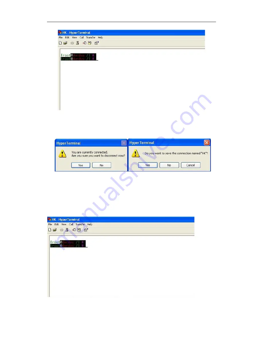
Disconnecting and saving the connection 

When  you disconnect the session, the following dialogue box pops out to ask  you whether  you want to save the 

session. If you save the session, the name of the session is kept and when the next time you use the Hyper Terminal 

Tools you can see an icon named with the session you saved.   


3.2 Network Configuration by Hyper Terminal 

After the successful connection of the Hyper Terminal, you can get to the operation interface of the hyper terminal 

interface. 


Содержание DS-6301DI

Страница 1: ...DS 6300DI Series Decoder USER MANUAL Version 3 2 0 ...

Страница 2: ...TION THE IMPLIED WARRANTIES OF MERCHANTABILITY AND FITNESS FOR A PARTICULAR PURPOSE REGARDING THE HIKVISION SOFTWARE HIKVISION DOES NOT WARRANT GUARANTEE OR MAKE ANY REPRESENTATIONS REGARDING THE USE OR THE RESULTS OF THE USE OF THE HIKVISION SOFTWARE IN TERMS OF ITS CORRECTNESS ACCURACY RELIABILITY CURRENTNESS OR OTHERWISE THE ENTIRE RISK AS TO THE RESULTS AND PERFORMANCE OF THE HIKVISION SOFTWAR...

Страница 3: ...s unsorted municipal waste in the European Union For proper recycling return this product to your local supplier upon the purchase of equivalent new equipment or dispose of it at designated collection points For more information see www recyclethis info 2006 66 EC battery directive This product contains a battery that cannot be disposed of as unsorted municipal waste in the European Union See the ...

Страница 4: ... serviceable parts inside the power supply System Grounding Earthing To avoid shock ensure that all AC wiring is not exposed and that the earth grounding is maintained Ensure that any equipment to which this device will be attached is also connected to properly wired grounded receptacles and are approved medical devices Power Connect and Disconnect The AC power supply cord is the main disconnect d...

Страница 5: ...nents such as heat sinks power regulators and processors may be hot care should be taken to avoid contact with these components Electro Magnetic Interference This equipment has not been tested for compliance with emissions limits of FCC and similar international regulations This device is not and may not be offered for sale or lease or sold or leased until authorization from the United States FCC ...

Страница 6: ...tch Please make sure the DVS work in the allowed range of temperature and humidity Please keep the device horizontal and avoid the installation under severe vibration environment The dust board will cause a short circuit after damping Please dedust regularly for the board connector chassis fan etc with brush Improper use or replacement of the battery may result in hazard of explosion Replace with ...

Страница 7: ...Connecting the decoder by Hyper Terminal Tools 17 3 2 Network Configuration by Hyper Terminal 19 C H A P T E R 4 21 Decoder Configuration and Operation by Client Software 21 4 1 Adding Modifying and Deleting the Decoder 22 4 1 1 Adding the Decoder to the Client Software 22 4 1 2 Deleting and Modifying the Decoder to the Client Software 24 4 2 TV Wall Layout Settings 24 4 3 Setting the Encoding Dev...

Страница 8: ...40 5 2 Parameter Configuration for Decoder 41 5 2 1 Checking Device Information 41 5 2 2 Configuring Time Settings 41 5 2 3 Configuring Basic Network Settings 42 5 2 4 Configuring Alarm Input Output Settings 42 5 2 5 Configuring Arming Time 43 5 2 6 Managing User Account 44 5 2 7 Rebooting Upgrading and Restoring the Default Settings for the Decoder 44 C H A P T E R 6 46 Appendix 46 Appendix A Spe...

Страница 9: ...User Manual of DS 6300DI Decoder 8 C H A P T E R 1 Introduction ...

Страница 10: ...mages with intelligent video analytics information Support PS RTP and private customized encapsulation formats PAL and NTSC image formats Decoding at 720P VGA SVGA 4CIF 2CIF DCIF CIF and QCIF image resolutions G 722 G 711A and G 711U video compression methods Decoding Resources DS 6308DI is capable of decoding 16 streams at CIF 8 streams at 4CIF 4 streams at 720P and it adopts 8 BNC and 4 VGA outp...

Страница 11: ...command to view device information modify network parameters etc Alarm Relay Alarm Input The decoder provides alarm input output ports in relay signal input mode which can be set to NO or NC Up to 8 different arming periods can be set in which the alarm occurs the device is capable of triggering corresponding alarm handling method relay output and buzzer alarm as well as upload to center etc Relay...

Страница 12: ...85 interface of decoder without any handling and the transparent channel of the decoder supports multi cast transparent transmission as well and multiple transparent channels can be established simultaneously PTZ Control Through SDK transparent channel the PTZ of DVR or DVS can be remotely controlled Two way Audio The decoder is capable of realizing voice talk with the remote client When the clien...

Страница 13: ...User Manual of DS 6300DI Decoder 12 C H A P T E R 2 Panel Connections ...

Страница 14: ...connector for voice talk input connect to active audio input device 3 LINE OUT 1 BNC connector for voice talk output connect to audio output device e g sound box 4 AUDIO 1 to AUDIO 4 Corresponding audio outputs of VGA1 to VGA4 BNC interface connect to audio output device 5 VGA VGA1 VGA4 connect to monitor 6 RS232 Connect to RS 232 devices e g PC etc 7 LAN 10 100 1000Mbps self adaptive UTP Ethernet...

Страница 15: ...e please follow the connections shown as below Alarm input connections for Emerson Alarm Alarm input connections for Normal Alarm 2 3 2 Alarm Output Connections DS 6300DI supports the open close relay input as the alarm output mode The alarm input can be selected to NO or NC Different alarm output connection methods are applied to the AC or DC load please refer to the following diagram Alarm outpu...

Страница 16: ...t And both of two jumpers are factory set to be connected 2 3 3 Signal Line Connections DS 6300DI Decoder provides the green terminal plug for connecting signal lines Follow the instructions shown below 1 Disconnect the green terminal plug from the terminal socket on the device 2 Use the standard screwdriver to loosen the screws on the plug and then insert signal lines to the plug and under the sp...

Страница 17: ...User Manual of DS 6300DI Decoder 16 C H A P T E R 3 Network Parameters Configuration ...

Страница 18: ...ind and configure the IP address and other parameters of the device For the operation of the SADP software please refer to the User Manual of the SADP software Note For the first time user the default user name of DS 6300DI is admin and password is 12345 And the default IP address is 192 0 0 64 3 1 Connecting the decoder by Hyper Terminal Tools Purpose By connecting decoder and PC with serial line...

Страница 19: ...ck OK to enter the Properties dialogue box 6 Set port parameters in COM1 Properties dialogue box shown as the following figure Bits per second 115200 Data bits 8 Parity None Stop bits 1 Flow control None 7 Click Apply and OK after the setup Press Enter under Hyper Terminal interface When root dvrdvs appears the connection is established ...

Страница 20: ... you want to save the session If you save the session the name of the session is kept and when the next time you use the Hyper Terminal Tools you can see an icon named with the session you saved 3 2 Network Configuration by Hyper Terminal After the successful connection of the Hyper Terminal you can get to the operation interface of the hyper terminal interface ...

Страница 21: ...Command format setIp IP mask e g setIp 192 168 1 10 255 255 255 0 getGateway Show current decoder gateway address Command format getGateway setGateway Set up gateway of the decoder Command format setGateway Gateway e g setGateway 192 168 1 1 Note Press Enter button to execute the command in the Hyper Terminal Tools And please strickly follow the format of the command lines otherwise the command yo...

Страница 22: ...User Manual of DS 6300DI Decoder 21 C H A P T E R 4 Decoder Configuration and Operation by Client Software ...

Страница 23: ...the decoder by the software is described Please refer to the User Manual of iVMS 4200 for more detailed information The following figure shows the main interface after accessing to the software 4 1 Adding Modifying and Deleting the Decoder 4 1 1 Adding the Decoder to the Client Software Steps 1 Click on the control panel to enter the decoding device management interfaces ...

Страница 24: ... name you customized and give to the decoder on the client software Or If you add the decoder with a private domain name you can check the checkbox before Private Domain Mode and enter the needed information 4 You can also click Show online devices to search the online devices in the same network segment And if there are online devices in the same network segment they are listed in the left part o...

Страница 25: ... to add the device to the management list 5 The successfully added device will be displayed on the list 4 1 2 Deleting and Modifying the Decoder to the Client Software After the successful adding of the device you can modify or delete the decoder from the management list Select the decoder on the device list and click Modify or Delete to modify or delete it 4 2 TV Wall Layout Settings ...

Страница 26: ...trol panel to enter the TV Wall setting interface The decoder configuration interface is shown as below 2 Click and drag the channels on the list of the decoding devices on the left bar to the TV Wall screen You can drag multiple decoding channels to the TV Wall ...

Страница 27: ...Bottom align Top align Horizontal Centralization Vertical Centralization Equal Height Equal Width 4 You can double click the channel or right click it and then click Modify on the decoding device list to modify the video output parameters 5 You can choose the video output standards and resolution of the decoding channel 4 3 Setting the Encoding Device for Decoding Channel After having configured t...

Страница 28: ...ing device can be a network camera DVR NVR or encoder In this configuration interface the left bar lists the encoding devices which have been added to the client software and the bottom bar with the configuration of the decoding action Description of the buttons on the bottom bar Button Description Button Description Showing Live View Alarm Decoding Mode PTZ Control Start Decoding Stop Decoding St...

Страница 29: ...the device list and click Remote Configuration The following prompt shows the interface for remote configuration you can check the general information of the device and configure the parameters for network settings user accounts alarms and so on For detailed information please refer to the User Manual of the iVMS 4200 Client Software ...

Страница 30: ...User Manual of DS 6300DI Decoder 29 C H A P T E R 5 Decoder Configuration Operation by Web Browser ...

Страница 31: ...coder by the web browser is provided Instruction The tested Web browsers include IE chrome safari and firefox4 Open the Web browser and input the IP address of Decoder e g http 172 9 108 36 to enter the login page Enter the user name and password of the Decoder in the dialog box and then click OK to log into the system By default the user name for login is admin and the password is 12345 Enter the...

Страница 32: ...the display configuration interface 2 You can select VGA or BNC display mode for configuration Note The HDMI and DVI are not supported by DS 6300 3 Select the display channel video standard PAL NTSC output resolution for VGA output BNC slim for BNC output and the screen mode Note Make sure the screen mode you select is supported by the current video output interface of the device E g the VGA1 of D...

Страница 33: ...b window click the button again and the following prompt will pop up as well Click OK to close the audio for the selected sub window and the Audio Status in the Sub Screen Information will be displayed in Enlarge Restore You can select the button to enlarge the selected sub window and display in full screen mode The following prompt will pop up Click OK to enlarge the selected sub window and the Z...

Страница 34: ... this function the output video image will be forcedly displayed at 640 576 on monitor 5 1 2 Dynamic Decode Dynamic decoding means that you decode one channel for one decoding window For example you can choose the first channel and then configure the corresponding device to be decoded for the channel Click Decode Operation Dynamic Decode to enter the Dynamic Decode interface The decode channel sta...

Страница 35: ...ogin to the encoding device Enable Stream Media Server Enable the stream media server if required and enter the IP address of the server After all settings have been configured click Start Dec button to start decoding and the decoding status can be viewed in the Connection Status or the Decode Channel Status interface 5 1 3 Cycle Decode Cycle decoding compared with the dynamic decoding means that ...

Страница 36: ...nterface to modify the device information Note Up to 64 cameras can be configured for each cycle decoding channel Example If you set the Decode Channel as Channel 1 and the Cycle Time as 10 seconds and set 10 decoding devices for the decode channel the image from these 10 devices are displayed for 10 seconds on the screen window for the channel in turn ...

Страница 37: ...ncoding device The Remote Host Channel refers to the channel number of the encoding device to be played back Remote playback by file enter the file name searched from DVR Remote playback by time enter the start time and end time of the record file 4 Click Save to finish the settings and click to start playback During the playback the buttons can be used to realize start stop slow forward fast forw...

Страница 38: ... interface 2 Select the decode channel in the dropdown list in the Decode Channel field 3 Select On or Off in the dropdown list in the Switch field 5 1 6 Image Scaling Purpose Image scaling function is to set the image display on the screen Steps 1 Click Decode Operation Decode Control Image Scale to enter the following interface 2 Select the decode channel in the dropdown list in the Decode Chann...

Страница 39: ... selected decode channel and the position of the picture overlaid on the screen can also be set here Steps 1 Click Decode Operation Decode Control Picture Overlay to enter the following interface 2 Select the decode channel in the dropdown list in the Decode Channel field 3 Browse to choose a picture in the local disks 4 Set the X coordinate and the Y coordinate of the picture displayed on the scr...

Страница 40: ...f the current decode channel including the channel number decode status encode type etc Refer to the following interface Note The Decode Channel Status of device will be refreshed automatically by regularly 5 1 10 Checking the Display Channel Status Purpose Display channel status interface shows the video output status of the decoder such as the status for the VGA output the status for the BNC out...

Страница 41: ...ort User Name Password of the encoding device In the list the Local Serial Port refers to the serial port used as the transparent channel by the Decoder while the Remote Serial Port refers to the serial port used as the transparent channel by the Encoder 3 Click Modify to finish the settings Click Refresh and the status in the Connection Status will be displayed as Connecting if the connection is ...

Страница 42: ...re Device Information to enter the following interface 2 Edit the device name and view the Device Type Device SN Firmware Version etc 5 2 2 Configuring Time Settings You can set the time for the decoder in the Time Settings interface Steps 1 Click Parameter Configure Parameter Configure Time Settings to enter the following interface 2 Select the NTP correction or Manual correction for the time set...

Страница 43: ... the IP Address Subnet Mask Gateway Address DNS Server etc 5 2 4 Configuring Alarm Input Output Settings Purpose As the Decoder is unable to obtain the alarm signal over network it must be connected with external alarm input output Steps Alarm Input Settings 1 Click Parameter Configure Alarm Parameters Alarm Input Settings to enter the following interface 2 Set the Alarm Mode for selected alarm in...

Страница 44: ...arm after the alarm output for example when you set the alarm output delay time as 10 seconds when an alarm occurs the alarming time lasts 10 seconds later than the time of the alarm stopped 3 Click Save to save your settings 5 2 5 Configuring Arming Time Purpose Set the time schedule for alarm input and alarm output Steps 1 Click Parameter Configure Arming Time to enter the following interface 2 ...

Страница 45: ...he following interface 2 You can add modify or delete the user as well as configure operating permissions to the users Note For the admin user account only the password can be modified 5 2 7 Rebooting Upgrading and Restoring the Default Settings for the Decoder Steps 1 To reboot upgrade or restore the default settings of the decoder go to the Device Management interface ...

Страница 46: ...e upgrading files 3 Click Upgrade to upgrade it To restore the default settings of the decoder 1 Click icon to enter the Restore Default interface 2 Click Complete to restore the completed factory settings of the decoder Or Click Simple to restore just a part of the factory settings of the decoder To reboot the decoder 1 Click icon to enter the rebooting interface 2 Click OK if you are sure to reb...

Страница 47: ...User Manual of DS 6300DI Decoder 46 C H A P T E R 6 Appendix ...

Страница 48: ...0Ω 6 ch BNC Linear electrical level 600Ω 12 ch BNC Linear electrical level 600Ω VGA Interface 1 ch Resolution 1280 1024 60 Hz 1280 720 60 Hz or 1024 768 60 Hz 2 ch Resolution 1280 1024 60 Hz 1280 720 60 Hz or 1024 768 60 Hz 4 ch Resolution 1280 1024 60 Hz 1280 720 60 Hz or 1024 768 60 Hz Communication Interface 1 RJ45 10 M 100 M 1000 M adaptive Ethernet interface 1 RS 232 interface 1 RS 485 interf...

Страница 49: ...68 512 384 256 128 64 kbps CBR support 2048 1536 1024 768 512 384 256 128 64 kbps Axis 207W 20 7MW 4 4 640 480 1280 1024 12 80 720 1280 960 1280 480 480 360 480 270 352 288 320 240 320 180 240 180 240 135 176 144 160 120 160 90 frame rate 25 20 15 10 8 6 5 4 3 2 1 VBR support 64 128 256 512 1024 1536 2048 3072 or self defined 32 8192 kbps CBR support 64 128 256 512 1024 1536 2048 3072 or self defi...

Страница 50: ... 704 576 704 288 352 288 176 144 not support frame rate settings Note the resolution actually supported is 640 480 320 240 or depending on different model VBR not support CBR support 2048 1536 1024 512 384 256 128 64 or self defined 32 8192 kbps NWC0495 18500400 640 480 320 240 704 576 704 288 352 288 176 144 not support frame rate settings Note the resolution actually supported is 704 576 704 288...

Страница 51: ...10 12 15 20 30N 25P Note the resolution actually supported is 640480 1280720 12809 60 or depending on different model CBR support 256 512 1M 2M 3M 4M 5M 6M 7M 8M kbps SD Network Camera Series 1 03 71 20091229 D1 2CIF CIF QCIF 640 480 1280 720 1280 9 60 frame rate 1 2 4 6 8 10 12 15 20 30N 25P Note the resolution actually supported is D1 2CIF CIF QCIF or depending on different model VBR support 256...

Страница 52: ... encoder Why cannot add decoder with software 1 Check the decoder IP 2 Make sure the cable is connected 3 User name and password of decoder are correct Why cannot play back the recorded file in DVR with decoder 1 Check the DVR network connection 2 Check the parameters of the Playback file 3 Check if there are files existed in the selected time range Why cannot decode the stream transported by stre...

Страница 53: ...ution The display resolution refers to the maximum display zone on the screen in certain display mode measured in horizontal and vertical pixel The image resolution describes the detail a digital image holds measured in horizontal and vertical pixel as well In case the image resolution is higher than the display resolution proportion of the image will not be displayed on the screen The pixel resol...

Страница 54: ...User Manual of DS 6300DI Decoder 53 Appendix E Revision History V3 0 1 Accessible by WEB browser 2 Support third party IP cameras refer to Appendix B 3 Enhance passive decoding capability ...

Отзывы: