


Camera
TVI DVR
Monitor
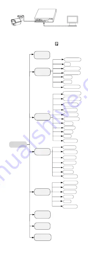
Figure 3-1
Connection
2.
Power on the camera, TVI DVR, and monitor to view
the image on the monitor.
3.
Click PTZ Control to enter the PTZ Control interface.
4.
Call the camera menu by clicking button or
calling preset No. 95.
EXPOSURE
EXPOSURE MODE
MAIN MENU
VIDEO
SETTINGS
FUNCTIONS
EXIT
SAVE & EXIT
AGC
BACK
EXIT
CONTRAST
SHARPNESS
SATURATION
3 DNR
MIRROR
BACK
BACK
EXIT
VIDEO
FORMAT
FACTORY
DEFAULT
SAVE & EXIT
WHITE BALANCE
BRIGHTNESS
EXIT
SAVE & EXIT
SAVE & EXIT
SLOW SHUTTER
IMAGE MODE
MOTION DET
PRIVACY
ANTI- BANDING
SMART
LIGHT
LIGHT
BACK
EXIT
SAVE & EXIT
THRESHOLD
LEVEL
MODE
ALARM MODE
Figure 3-2
Main Menu Overview


