


Network Video Recorder User Manual
68
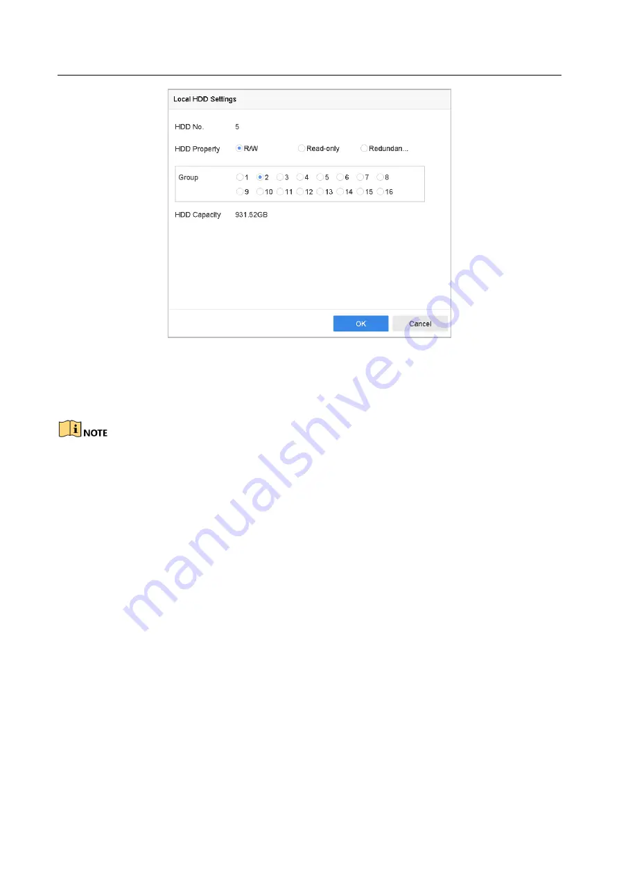
Figure 7-5
Local HDD Settings
Step 4
Select the Group number for the current HDD.
Step 5
Click OK.
Regroup the cameras for HDD if the HDD group number is changed.
Step 6
Go to Storage> Storage Mode.
Step 7
Check the checkbox of Group tab.
Step 8
Select the group No. from the list.
Step 9
Check the checkbox to select the IP camera (s) to record on the HDD group.
Содержание DeepinMind Super iDS-96064NXI-I16
Страница 1: ...Network Video Recorder User Manual...
Страница 158: ...Network Video Recorder User Manual 156 Figure 16 6 Port Settings...
Страница 199: ...Network Video Recorder User Manual 197 UD10737B...


