X86 Open Platform
·
User Manual
3
2
3
4
5
6
7
8
9
1
10
11
12
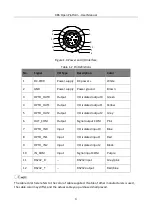
Figure 1-4
Power and I/O Interface
Table 1-2
Pin Definitions
No.
Signal
I/O Type
Description
Color
1
DC-PWR
Power supply DC power +
White
2
GND
Power supply Power ground
Brown
3
OPTO_OUT0
Output
I/O isolated output 0
Green
4
OPTO_OUT1
Output
I/O isolated output 1
Yellow
5
OPTO_OUT2
Output
I/O isolated output 2
Grey
6
OUT_COM
Output
Signal output COM
Pink
7
OPTO_IN0
Input
I/O isolated input 0
Blue
8
OPTO_IN1
Input
I/O isolated input 1
Red
9
OPTO_IN2
Input
I/O isolated input 2
Black
10
IN_COM
Input
Signal input COM
Purple
11
RS232_R
--
RS232 input
Grey/pink
12
RS232_T
--
RS232 output
Red/blue
The cable color here refers to the color of cable supplied. If cable of other manufacturers is used,
the cable color may differ, and the actual cable you purchased shall prevail.
Содержание X86
Страница 1: ...X86 Open Platform User Manual ...
Страница 7: ...X86 Open Platform User Manual vii E mail tech_support hikrobotics com Website en hikrobotics com ...
Страница 38: ...X86 Open Platform User Manual 28 Figure 6 3 Set Output Delay Duration or Ahead Time ...
Страница 67: ...X86 Open Platform User Manual 57 Figure 10 17 Select MVision 6 Connect device and obtain images ...
Страница 75: ...UD15058B ...


