background image

CA/CE-Series GigE Area Scan Camera

·

User Manual 

27 

Steps:


1.


Click 

Acquisition Control 

Acquisition Burst Frame Count

2.


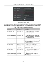
Enter proper value according to actual demands. Its range is from 1 to 1023. 


Figure 7-13


Set Burst Frame Count 

When 

Acquisition  Burst  Frame  Count

  is  1,  it  is  in  single  frame  trigger  mode.  When 

Acquisition 

Burst Frame Count 

is larger than  1, it  is in multi-frame trigger mode. If 

Acquisition Burst Frame 

Count

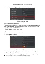
 is n and when inputting 1 trigger signal, the camera stops acquiring images after exposing n 

times and outputs n frame images. The sequence diagram of burst frame count is shown below. 

Trigger

Sensor 

exposure

Burst Count = 4


Figure 7-14


Sequence Diagram of Burst Frame Count 

7.5.2 Set Trigger Delay 

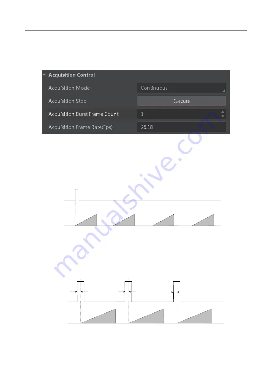
From camera receiving signal and responding, this period is trigger delay. Its sequence diagram is 
shown below. 

Sensor 

exposure

Exposure 1

Exposure 2

Exposure 3

Trigger_in 1

Trigger 

delay

Trigger_in 2

Trigger 

delay

Trigger_in 3

Trigger 

delay


Figure 7-15


Signal Delay Sequence Diagram 

Содержание CA Series

Страница 1: ...CA CE Series GigE Area Scan Camera User Manual ...

Страница 2: ...ILITY SATISFACTORY QUALITY OR FITNESS FOR A PARTICULAR PURPOSE THE USE OF THE PRODUCT BY YOU IS AT YOUR OWN RISK IN NO EVENT WILL HIKROBOT BE LIABLE TO YOU FOR ANY SPECIAL CONSEQUENTIAL INCIDENTAL OR INDIRECT DAMAGES INCLUDING AMONG OTHERS DAMAGES FOR LOSS OF BUSINESS PROFITS BUSINESS INTERRUPTION OR LOSS OF DATA CORRUPTION OF SYSTEMS OR LOSS OF DOCUMENTATION WHETHER BASED ON BREACH OF CONTRACT TO...

Страница 3: ...s been tested and found to comply with the limits for a Class A digital device pursuant to part 15 of the FCC Rules These limits are designed to provide reasonable protection against harmful interference in a residential installation This equipment generates uses and can radiate radio frequency energy and if not installed and used in accordance with the instructions may cause harmful interference ...

Страница 4: ... www recyclethis info 2006 66 EC battery directive This product contains a battery that cannot be disposed of as unsorted municipal waste in the European Union See the product documentation for specific battery information The battery is marked with this symbol which may include lettering to indicate cadmium Cd lead Pb or mercury Hg For proper recycling return the battery to your supplier or to a ...

Страница 5: ... the device may be damaged Avoid sudden collision and pack the device with the accompanied carton and cushioning material or similar package Using Environment In order to reduce the risk of fire or electric shock do not let the device get wet or damp Do not drop objects onto the device and avoid vigorous vibration Keep the device away from magnetic interference Do not use the device in extremely h...

Страница 6: ...device so that when problems arise the device can be packed with packaging materials and sent to the agent or returned to the manufacturer for processing The company does not bear any liability for accidental damage during transportation caused by non original packaging This device is a precision electronic device no components can be maintained by user do not disassemble the device arbitrarily Cl...

Страница 7: ...CA CE Series GigE Area Scan Camera User Manual vii E mail tech_support hikrobotics com Website en hikrobotics com ...

Страница 8: ...Camera Settings 10 5 1 Main Window 10 5 2 Set Parameters 11 Chapter 6 Camera Features 14 6 1 Global Shutter 14 6 2 Rolling Shutter 15 6 3 Non Overlap Exposure and Overlap Exposure 15 6 3 1 Non Overlap Exposure 16 6 3 2 Overlap Exposure 16 Chapter 7 Image Acquisition 18 7 1 Set Frame Rate 18 7 2 Set Acquisition Mode 19 7 3 Set Trigger Mode 20 7 4 External Trigger Mode 21 7 4 1 Set External Trigger ...

Страница 9: ...rter 35 8 2 2 Enable Strobe Signal 36 Chapter 9 I O Electrical Feature and Wiring 41 9 1 I O Electrical Feature 41 9 1 1 Line 0 Opto isolated Input Circuit 41 9 1 2 Line 1 Opto isolated Output Circuit 42 9 1 3 Line 2 Bi direction I O Circuit 43 9 2 I O Wiring 46 9 2 1 Line 0 Wiring 46 9 2 2 Line 1 Wiring 47 9 2 3 Line 2 Wiring 48 Chapter 10 Image Parameter 50 10 1 Check Resolution 50 10 2 Set ROI ...

Страница 10: ... 66 10 18 Set Embedded Information in Image 66 Chapter 11 Other Functions 69 11 1 Device Control 69 11 2 File Access Control 71 11 3 Save and Load User Set 71 11 4 Set Transport Layer Control 73 11 4 1 DHCP and Persistent IP 73 11 4 2 Effective Bandwidth and Setting 74 11 5 Update Firmware 74 Chapter 12 Trouble Shooting 76 Chapter 13 Revision History 77 Appendix A Camera Parameter Index 78 ...

Страница 11: ...ight interface position difference as shown below You should use M3 or M2 screw to install the camera to a position For specific appearance and dimensions please refer to the camera s specification for details The appearance is subject to change and the actual device you purchased shall prevail Figure 1 1 Appearance Type I Figure 1 2 Appearance Type II Figure 1 3 Appearance Type III ...

Страница 12: ...GigE area scan camera has 3 kinds of appearance and here we take type I as an example for interface introduction 1 2 Power and I O Interface The description of the 6 pin power and I O interface is shown in Table 1 2 Table 1 2 Pin Definition Illustration No Signal I O Signal Source Description 1 2 3 4 5 6 1 DC_PWR DC Power 2 Opt Iso In Line 0 signal line Opto isolated input 3 GPIO Line 2 signal lin...

Страница 13: ...t is flashing very slowly Network error 2 Blue indicator It is flashing slowly The camera is acquiring images in trigger mode 3 Blue indicator It is flashing fast The camera is acquiring images normally 4 Blue indicator It is solid The camera is in idle status 5 Red blue indicator Red blue indicator flash alternatively The function of finding me is executed 6 Red blue indicator Red blue indicator ...

Страница 14: ...ith a switch or a network card to guarantee the bandwidth for real time image transmission Before you start Make sure all the related devices are power off during the installation Steps 1 Install the lens to the lens mount 2 Fix the camera to the desired position 3 Use network cable to connect the camera with a switch or a network card 4 Select a power supply method Direct supply Use the cable wit...

Страница 15: ...indows as an example Software version in this manual is V3 1 0 If other versions are used the graphic user interface may differ You can download Windows version client software from en hikrobotics com For other versions of client software please contact technical support personnel via e mail tech_support hikrobotics com to obtain it Steps 1 Double click MVS installation package to install the clie...

Страница 16: ...ove link efficiency and the later ensures the connection between the device and the computer Steps 1 After installing MVS client click Start Menu of the PC to find NIC_Configurator 2 Click NIC_Configurator to run it 3 Enable Jumbo Frame Figure 3 2 Set Jumbo Packet 4 Click Open in the Internet Protocol select Obtain an IP address automatically and click OK to save Figure 3 3 Local NIC Settings ...

Страница 17: ...f the device Before you start Make sure the device is powered on and connected to the network Make sure your computer is connected to the same network with that of the device Only when the device is in the same network segment with the computer can you operate the device via the MVS For MVS below V3 0 0 please turn off the firewall in your PC Steps 1 Run the MVS client software 2 Click Tools IP Co...

Страница 18: ...tart automatically Change the IP address if the modified IP address conflicts with another device s IP address in the same local subnet The parameters in the figure are only for reference Please enter the parameters according to the actual situation 3 4 Connect Camera to MVS Before you start Power on the camera Make sure your camera and the PC are in the same network segment Steps 1 Run the MVS cl...

Страница 19: ...lick to connect the camera and then click to start acquisition as shown below Software version in this manual is V3 1 0 If other versions are used the graphic user interface and icon may differ Figure 4 1 Live View in the MVS Table 4 1 Icon Description No Icon Description 1 Connect or disconnect camera 2 Start or stop acquisition 3 Start batch acquisition 4 Stop batch acquisition 5 Start or stop l...

Страница 20: ...dow of the MVS Client For specific main window of the MVS client please refer to the actual one you got Table 5 1 Description of the Main Window No Area Name Description 1 Menu Bar Function modules including File View Settings Tool and Help 2 Control Toolbar The control toolbar provides quick operations for camera images 3 Device List Panel Display the GigE Vision cameras USB3 Vision cameras and C...

Страница 21: ...ted camera and perform other operations such as importing exporting and saving features You can refer to the MVS User Manual for detailed MVS operations by clicking Help User Manual in the MVS software 5 2 Set Parameters The camera setting supports 3 kinds of user level Beginner Expert or Guru which displays different camera attributes For Guru Level it provides the most comprehensive camera attri...

Страница 22: ...ce color transformation related parameters LUT Control You can view the Look Up Table LUT and set its index and value Digital IO Control You can set the different input and output signals Action Control You can view and set the device action control related parameters Counter And Timer Control You can set the function of Counter 0 as trigger source File Access Control You can view and set the devi...

Страница 23: ...n Transport Layer Control You can set the parameters of transport layer of the device User Set Control You can save or load the device s parameters You can set the default parameter when running the client For specific attributes please refer to the actual device you got ...

Страница 24: ... expose at the same time then readout at different time as shown below Line 1 Line 2 Line 3 Line 4 Line 5 Line n Line n 1 Readout Readout Exposure Figure 6 1 Global Shutter The figure of global shutter s signal readout under internal trigger mode Sensor exposure Exposure 1 Exposure 2 Exposure 3 Frame 1 Readout Frame 2 Readout Figure 6 2 Signal Readout under Internal Trigger Mode The figure of glob...

Страница 25: ...pixels expose at the same time then readout at different time as shown below Line 1 Line 2 Line 3 Line 4 Line 5 Line n Line n 1 Readout Readout Exposure Offset Readout Figure 6 4 Rolling Shutter The figures of rolling shutter s signal readout under internal trigger mode and external trigger mode are the same with those of global shutter as shown above 6 3 Non Overlap Exposure and Overlap Exposure ...

Страница 26: ... Frame2 Readout Figure 6 5 Internal Trigger Non Overlap Exposure Non overlap Exposure under External Trigger Mode Trigger_in 1 Trigger_in 2 Trigger_in 3 Sensor exposure Exposure 1 Exposure 2 Exposure 3 Frame1 Readout Frame2 Readout Figure 6 6 External Trigger Non Overlap Exposure The camera will ignore the external signal in the readout section under this mode 6 3 2 Overlap Exposure Overlap exposu...

Страница 27: ...gure 6 7 Internal Trigger Overlap Exposure Overlap Exposure under External Trigger Mode Sensor exposure Exposure 1 Exposure 2 Exposure 3 Trigger_in 1 Trigger_in 2 Trigger_in 3 Frame 1 Readout Frame 2 Readout Figure 6 8 External Trigger Overlap Exposure The camera will ignore the external signal in the readout section under this mode ...

Страница 28: ...te that the camera supports is t and when the configured exposure time is larger than t the less the exposure time the higher the frame rate will be When the configured exposure time is less than or equal to t exposure time will not influence the frame rate Bandwidth the larger the bandwidth the higher the frame rate will be Pixel format the more bytes pixel format occupy the lower the frame rate ...

Страница 29: ...ting Frame Rate 7 2 Set Acquisition Mode The camera has 2 types of acquisition modes including SingleFrame mode and Continuous mode Under SingleFrame mode the camera will automatically stop acquisition after acquiring 1 image Under Continuous mode the camera acquires images continuously and it will not stop until user stops it manually Steps 1 Click Acquisition Control Acquisition Mode 2 Select Co...

Страница 30: ...on Control Trigger Mode Off The camera acquires images via its internal signals External trigger mode Acquisition Control Trigger Mode On The camera acquires images via external signals These signals can be software signal and hardware signal including software trigger hardware trigger counter trigger and frame grabber trigger You can set trigger mode as shown below Steps 1 Click Acquisition Contr...

Страница 31: ...ardware trigger Acquisition Control Trigger Source Line 0 Line 2 External device connects camera via camera I O interface External device sends trigger signal to camera to acquire images Counter trigger Acquisition Control Trigger Source Counter 0 The counter sends trigger signal to the camera to acquire images Action command trigger Acquisition Control Trigger Source Action 1 The action command s...

Страница 32: ...as shown below Steps 1 Click Acquisition Control Trigger Selector 2 Select Frame Burst Start as Trigger Selector and On as Trigger Mode 3 Select Software as Trigger Source and click Execute in Trigger Software to send trigger commands Figure 7 6 Set Software Trigger 7 4 3 Set Hardware Trigger The camera has 1 Opto isolated input Line 0 and 1 bi directional I O Line 2 that can be configured as inpu...

Страница 33: ...Line 2 as Trigger Source Here we take Line 0 as an example Figure 7 8 Set Hardware Trigger 7 4 4 Set Counter Trigger The counter trigger provides frequency division to the external trigger signal You can set counter trigger as shown below Steps 1 Click Acquisition Control Trigger Selector 2 Select Frame Burst Start as Trigger Selector and On as Trigger Mode 3 Select Counter 0 as Trigger Source ...

Страница 34: ...is available only at present Counter Event Source Read and write It selects the signal source of counter trigger Line 0 and Line 2 are available It is disabled by default Counter Reset Source Read and write It selects the signal source of resetting counter Software is available only It is disabled by default Counter Reset Write is available under certain condition It resets counter and it can be e...

Страница 35: ... Steps 1 Click Acquisition Control Trigger Selector 2 Select Frame Burst Start as Trigger Selector and On as Trigger Mode 3 Select Action 1 as Trigger Source Figure 7 11 Set Action Command Trigger For specific function of action commands please refer to Section 7 8 Action Commands for details 7 4 6 Set Anyway Trigger When you need to use both hardware trigger and software trigger you can set Anywa...

Страница 36: ...t various trigger parameters and their relation is shown below Table 7 4 Trigger Source and Trigger Parameter Trigger Source Trigger Parameter Software Trigger Hardware Trigger Counter Trigger Action Command Trigger Any Trigger Burst Frame Count Support Support Support Support Support Trigger Delay Support Support Support Support Support Trigger Cache Enable Support Support Support Support Support...

Страница 37: ...tion Burst Frame Count is n and when inputting 1 trigger signal the camera stops acquiring images after exposing n times and outputs n frame images The sequence diagram of burst frame count is shown below Trigger Sensor exposure Burst Count 4 Figure 7 14 Sequence Diagram of Burst Frame Count 7 5 2 Set Trigger Delay From camera receiving signal and responding this period is trigger delay Its sequen...

Страница 38: ...gnal if you enable this function Trigger cache enable can save up to 2 trigger signals You can set Trigger Cache Enable as shown below Steps 1 Click Acquisition Control Trigger Cache Enable 2 Enable Trigger Cache Enable Figure 7 17 Enable Trigger Cache Enable If the camera receives the 1st trigger signal first and the camera receives the 2nd trigger signal during processing the 1st trigger signal ...

Страница 39: ...e 7 5 Trigger Activation Principle and Parameter Trigger Activation Parameter Parameter Value Principle Rising edge Acquisition Control Trigger Activation Rising Edge Rising Edge refers to the rising edge of the trigger signal is valid that is camera exposure and acquisition at the beginning of the rising edge of the trigger signal Falling edge Acquisition Control Trigger Activation Falling Edge F...

Страница 40: ...unce that may cause false trigger Thus it is necessary to debounce the external trigger signal and its sequence diagram is shown below Before debounce After debounce Trigger_in1 Trigger_in2 Trigger_in3 Trigger_in2 Trigger_in3 Debouncer Time Debouncer Time Debouncer Time t1 t2 t3 t4 t5 t6 t1 t2 trigger signal is ignored t3 t4 trigger signal outputs after delaying t3 t5 t6 trigger signal outputs aft...

Страница 41: ...enerate an event and transmit a related event message to the computer whenever a specific situation occurs You can set event control as shown below Steps 1 Click Event Control 2 Select specific event in Event Selector for example Acquisition Start 3 Select Notification On as Event Notification Figure 7 21 Set Event Control 7 7 Chunk Data Control The chunk data control function allows you to genera...

Страница 42: ...es in a pre defined group respond based on how they have been configured to respond to certain commands In MVS action command is usually used for generating images in multiple cameras simultaneously and the generated images can be used for image fusion The action commands function is available only with client software version of V3 1 0 and higher This function should be supported by the device an...

Страница 43: ...ask against the ActionGroupMask feature should results in non zero 4 Enable Scheduled 5 Click in Benchmark Camera to select one camera from drop list as benchmark camera Once benchmark camera is selected other cameras keep time synchronization with it 6 Optional Enter proper value in Delay Time The delay time should NOT be shorter than the maximum time required to transmit the command across the n...

Страница 44: ...tion commands that are executed in multiple cameras at exactly the same time it is recommended to enable Gev IEEE 1588 first by clicking Transport Layer Control Gev IEEE 1588 7 9 Color Transformation Control The camera supports Color Correction Matrix function that is designed to restore color and eliminate the overlap in the color channels caused by the fact that Blue light is seen by the Red and...

Страница 45: ...et Output Signal The output signal of the camera is switch signal which is used to control external devices such as light source etc There are two ways to realize trigger output signal including level inverter and strobe signal 8 2 1 Enable Level Inverter The level inverter function is used to control the camera s output signal manually You can enable level inverter function via setting line inver...

Страница 46: ...to directly output I O signal to external devices when camera s event source occurs You can enable strobe signal as shown below Steps 1 Click Digital IO Control 2 Select different output events as Line Source according to actual demands 3 Enable Strobe Enable Figure 8 3 Set Line Source For specific Line Source please refer to following table for details ...

Страница 47: ...Active It refers to output one I O edge signal when stopping triggering and acquiring images under Burst mode 6 Soft Trigger Out It refers to output one I O edge signal when software trigger acquisition 7 Hard Trigger Active It refers to output one I O edge signal when hardware trigger acquisition 8 Count Active It refers to output one I O edge signal when counter output is enabled 9 Timer Active ...

Страница 48: ...l to Strobe Line Duration value Set Strobe Line Delay The camera supports setting strobe line delay to meet actual demands When exposure starts the strobe output doesn t take effect immediately Instead the strobe output will delay according to the strobe line delay setting You can set strobe line delay as shown below Steps 1 Click Digital IO Control Strobe Line Delay 2 Enter proper value in Strobe...

Страница 49: ...Trigger delay Figure 8 6 Sequence Diagram of Strobe Line Delay Set Strobe Line Pre Delay The camera also supports the function of strobe line pre delay which means that the strobe signal takes effect early than exposure This function is applied to the external devices that have slow response speed You can set strobe line pre delay as shown below Steps 1 Click Digital IO Control Strobe Line Pre Del...

Страница 50: ...Delay The sequence diagram of strobe line pre delay is shown below Strobe Trigger_in 1 Sensor exposure Exposure 1 Exposure 2 Exposure 3 Trigger delay Trigger_in 2 Trigger delay Trigger_in 3 Trigger delay Duration Strobe pre delay Figure 8 8 Sequence Diagram of Strobe Line Pre Delay ...

Страница 51: ...circuit in camera I O control is shown below Line 0 GPI Line 0 VCC Figure 9 1 Line 0 Internal Circuit The maximum input current of Line 0 is 25 mA Logic 1 Input Level Logic 0 Input Level Internal Logic TDR TDF Figure 9 2 Input Logic Level Table 9 1 Input Electrical Feature Parameter Name Parameter Symbol Value Input Logic Level Low VL 0 VDC to 1 VDC Input Logic Level High VH 1 5 VDC to 24 VDC ...

Страница 52: ...n voltage is 30 VDC and keep voltage stable 9 1 2 Line 1 Opto isolated Output Circuit The Line 1 opto isolated output circuit in camera I O control is shown below GPO Line 1 Line 1 Figure 9 3 Line 1 Internal Circuit The maximum output current of Line 1 is 25 mA Logic 1 Output Level Logic 0 Output Level Internal Logic TDR TDF Figure 9 4 Output Logic Level Opto isolated output electric feature is sh...

Страница 53: ...oltage and resistance the corresponding current and the parameter of output logic level low are shown below Table 9 3 Parameter of Output Logic Level Low External Voltage External Resistance VL Output Current 3 3 V 1 KΩ 575 mV 2 7 mA 5 V 1 KΩ 840 mV 4 1 mA 12 V 2 4 KΩ 915 mV 4 6 mA 24 V 4 7 KΩ 975 mV 4 9 mA 9 1 3 Line 2 Bi direction I O Circuit The Line 2 bi direction I O circuit in camera I O con...

Страница 54: ... Level High VH 1 5 VDC to 30 VDC Input Rising Time TR 0 66 μs Input Falling Time TF 0 05 μs Make sure the input voltage is not from 0 5 VDC to 1 5 VDC as the electric status between these two values are not stable The breakdown voltage is 30 VDC and keep voltage stable To prevent damage to the GPIO pin please connect GND first and then input voltage in Line 2 Line 2 Configured as Output When the e...

Страница 55: ...of external resistance 1KΩ is pulled up to 5V the logic level and electrical feature of configuring Line 2 as output are shown below Logic 1 Output Level Logic 0 Output Level Internal Logic TDR TDF TF TR Figure 9 7 Output Logic Level Table 9 6 Electrical Feature of Line 2 Output Parameter Name Parameter Symbol Value Output Rising Time TR 0 06 μs Output Falling Time TF 0 016 μs Output Rising Delay ...

Страница 56: ...n Camera Power Ground PWR VCC Device Power Supply Signal Line Device Power Ground PNP Device I O Ground GND of PWR GND of VCC Figure 9 8 Line 0 Connecting to PNP Device NPN Device If the VCC of NPN device is 24 VDC and it is recommended to use 1 KΩ to 4 7 KΩ pull up resistor If the VCC of NPN device is 12 VDC and it is recommended to use 1 KΩ pull up resistor Camera Power Supply Opt Iso in Camera ...

Страница 57: ...era Power Ground PWR VCC Device Power Supply Signal Line Device Power Ground PNP Device I O Ground GND of PWR GND of VCC Figure 9 11 Line 1 Connecting to PNP Device NPN Device If the VCC of NPN device is 24 VDC and it is recommended to use 1 KΩ to 4 7 KΩ pull up resistor If the VCC of NPN device is 12 VDC and it is recommended to use 1 KΩ pull up resistor Camera Power Supply Opt Iso out Camera Pow...

Страница 58: ...evice Power Supply Signal Line PNP Device GND of PWR and VCC Device Power Ground Figure 9 13 Line 2 Connecting to PNP Device as Input NPN Device If the VCC of NPN device is 24 VDC and it is recommended to use 1 KΩ to 4 7 KΩ pull up resistor If the VCC of NPN device is 12 VDC and it is recommended to use 1 KΩ pull up resistor Camera Power Supply Bi direction I O Camera Power Ground PWR VCC Device P...

Страница 59: ...n I O Camera Power Ground PWR VCC Device Power Supply Signal Line PNP Device GND of PWR and VCC Device Power Ground Figure 9 16 Line 2 Connecting to PNP Device as Output NPN Device If the VCC of NPN device is 24 VDC and it is recommended to use 1 KΩ to 4 7 KΩ pull up resistor If the VCC of NPN device is 12 VDC and it is recommended to use 1 KΩ pull up resistor Camera Power Supply Bi direction I O ...

Страница 60: ...OI for the camera Setting Region of Interest can reduce the bandwidth of the image being transmitted Thus increasing the frame rate to some extent The camera currently supports 1 ROI only that is there is Region 0 for Region Selector parameter only Region of interest can be set only when you stop real time acquisition Steps 1 Click Image Format Control Region Selector 2 Set proper value in Width H...

Страница 61: ...els of camera the above mentioned setting steps may be different please refer to the actual one you got 10 3 Set Image Reverse The camera supports horizontal and vertical reverse image output Horizontal reverse refers to the image reverses in a horizontal way and vertical reverse refers to the image reverses in a vertical way You can set image reverse as shown below Steps 1 Click Image Format Cont...

Страница 62: ...models of camera the image reverse function may be different please refer to the actual one you got 10 4 Set Pixel Format The camera supports many pixel formats For specific pixel formats that the camera supports please refer to the specifications of the camera The corresponding numbers of bytes to different formats are shown below ...

Страница 63: ...et pixel format as shown below Steps 1 Click Image Format Control Pixel Format 2 Set Pixel Format according to actual demands Figure 10 5 Set Pixel Format 10 5 Set Test Pattern The camera supports test pattern function When there is exception in real time image you can check whether image of test mode have similar problem to determine the reason This function is disabled by default and at this poi...

Страница 64: ...tern 2 Set Test Pattern according to actual demands Figure 10 6 Set Test Pattern The mono camera offers 4 test patterns including Mono Bar Checkboard Oblique Mono Bar and Gradual Mono Bar For color camera it also supports Vertical Color Bar and Horizontal Color Bar Figure 10 7 Mono Bar Test Pattern Figure 10 8 Checkboard Test Pattern ...

Страница 65: ...CA CE Series GigE Area Scan Camera User Manual 55 Figure 10 9 Oblique Mono Bar Test Pattern Figure 10 10 Gradual Mono Bar Test Pattern Figure 10 11 Vertical Color Bar Test Pattern ...

Страница 66: ...th binning multiple sensor pixels are combined as a single pixel to reduce resolution and improve image brightness You can set binning as shown below Steps 1 Click Image Format Control 2 Select proper value in Binning Horizontal and Binning Vertical Figure 10 13 Set Binning Binning Horizontal refers to the image s width and Binning Vertical refers to the image s height For different models of came...

Страница 67: ... function may be different please refer to the actual one you got 10 8 Set Exposure Mode The camera supports exposure function For specific exposure range that the camera supports please refer to the specifications of the camera The camera has 3 types of exposure Off Once and Continuous The exposure mode and principle are shown below Table 10 2 Exposure Mode and Principle Exposure Mode Parameter P...

Страница 68: ...amera is under Continuous exposure mode once external trigger mode is enabled the camera will automatically switch to Off exposure mode 10 9 Set Gain The camera supports gain function For specific gain range that the camera supports please refer to the specifications of the camera The camera has 3 types of gain modes Off Once and Continuous The gain mode and principle are shown below Table 10 3 Ga...

Страница 69: ...se will increase too which will influence image quality If you want to increase image grayscale value it is recommended to increase the camera s exposure time If the exposure time reaches its upper limit and at this point you can increase analog gain 10 10 Set Brightness The camera brightness refers to the brightness when the camera adjusts image under Once or Continuous exposure mode or Once or C...

Страница 70: ...to change the overall brightness of an image by changing the gray values of the pixels by a specified amount The range of black level is from 0 to 4095 You can set black level as shown below Steps 1 Click Analog Control and enable Black Level Enable 2 Enter proper value in Black Level according to actual demands Figure 10 18 Set Black Level 10 12 Set White Balance White balance is only available f...

Страница 71: ... stop It implements an algorithm that finds possible gray areas in the Bayer data Continuous Analog Control Balance White Auto Continuous Continuous automatic white balance It implements an algorithm that finds possible gray areas in the Bayer data Steps 1 Click Analog Control Balance White Auto 2 Select Off as Balance White Auto 3 Select Balance Ratio Selector and Balance Ratio according to actua...

Страница 72: ...face of the sensor Gamma correction provides a non linear mapping mechanism as shown below Gamma value between 0 5 and 1 image brightness increases dark area becomes brighter Gamma value between 1 and 4 image brightness decreases dark area becomes darker In the format of Bayer the color camera does not have Gamma correction function 1 0 9 0 8 0 7 0 6 0 5 0 4 0 3 0 2 0 1 0 9 0 8 0 7 0 6 0 5 0 4 0 3...

Страница 73: ...d its range is from 0 to 4 Figure 10 22 Set User Mode You can set sRGB mode as shown below Steps 1 Click Analog Control Gamma Selector 2 Select sRGB as Gamma Selector 3 Enable Gamma Enable Figure 10 23 Set sRGB Mode The Gamma correction function is disabled by default 10 14 Set Hue and Saturation Only the color camera supports hue and saturation function Hue Adjusting the hue shifts the colors of ...

Страница 74: ...unction Saturation Adjusting the saturation changes the colorfulness of the colors A higher saturation for example makes colors easier to distinguish Steps 1 Click Color Transformation Control Saturation Enable 2 Enable Saturation Enable 3 Enter proper value in Saturation according to actual demands and its range is from 0 to 255 Figure 10 25 Set Saturation In the format of Bayer the color camera ...

Страница 75: ...lso set AOI and the camera will adjust the brightness and white balance of the entire image based on the area you selected Steps 1 Click Analog Control Auto Function AOI Selector 2 Select AOI 1 or AOI 2 AOI 1 adjusts image brightness and AOI 2 adjusts white balance for color camera 3 Enter proper value in Auto Function AOI Width Auto Function AOI Height Auto Function AOI Offset X and Auto Function...

Страница 76: ...1 Click LUT Control 2 Enable LUT Enable 3 Enter proper value in LUT Index according to actual demands and its range is from 0 to 1023 4 Enter proper value in LUT Value according to actual demands and its range is from 0 to 4095 Figure 10 28 Set LUT You cannot use Gamma correction function and LUT function at the same time In the format of Bayer the color camera does not have LUT function 10 18 Set...

Страница 77: ... Brightness Info 4 Bytes 4 bytes are used to transfer the brightness information Value Range 0 to 4095 Note High bits will be complemented with 0 automatically 5 White Balance 8 Bytes 8 bytes are used to transfer the white balance information Value Range 0 to 4095 6 Frame Counter 4 Bytes Value Range 0 to 232 1 7 Ext Trigger Counter 4 Bytes Value Range 0 to 232 1 8 Line Input Output 4 Bytes 4 bytes...

Страница 78: ... there is not enough space in first line image and then the collection information will be embedded into the second line image The low 8 bit of each valid data storages image embedded information You can set embedded information in image as shown below Steps 1 Click Image Format Control Embedded Image Info Selector 2 Select respective parameters from drop down list Figure 10 29 Set Embedded Inform...

Страница 79: ...t is the device model Device Manufacture Info Read only It is the manufacturer information Device Version Read only It is the device version Device Firmware Version Read only It is the device firmware version Device Serial Number Read only It is the device serial number Device ID Read only It is the device ID Device User ID Read and write Device name and it is empty by default You can set accordin...

Страница 80: ...ity Device Stream Channel Selector Read and write It is the character set used in register Device Stream Channel Type Read only It is the stream channel type Device Stream Channel Link Read only It is the stream channel link quantity Device Stream Channel Endianness Read only It is the image data endianness Device Stream Channel Packet Size B Read and write It is the data packet size Device Event ...

Страница 81: ...on or DPC information from the local PC to a connected device This function should be supported by the device and it is not available if you start acquisition This function is related with User Set not the current parameters you set Setting User Set Save or User Set Load first if you want to link this function with the current parameters Steps 1 Click to open the File Access interface Figure 11 1 ...

Страница 82: ...t as shown below Save Parameters Steps 1 Click User Set Control and select a user set in User Set Selector Here we take selecting User Set 1 as an example 2 Click Execute in User Set Save to save parameters Figure 11 3 Save User Set Load Parameters Steps 1 Click User Set Control and select a user set in User Set Selector Here we take selecting User Set 1 as an example 2 Click Execute in User Set L...

Страница 83: ...t Transport Layer Control 11 4 1 DHCP and Persistent IP The camera supports connecting with PC through DHCP or persistent IP as shown below The camera will acquire IP according to the following order 1 If the camera s static IP function is enabled and the configured persistent IP is available and the camera will load the persistent IP otherwise execute 2 2 If DHCP function is enabled and the acqui...

Страница 84: ...36 Mbps The actual network bandwidth is smaller than the theoretical one because of the network message GVCP GCSP leader Trailer and any other overheads You can set Packet Size GEV SCPS Packet Size value and Packet Delay GEV SCPD value by input value in the input box as shown below Figure 11 7 Set Packet Size and Packet Delay 11 5 Update Firmware The camera supports firmware updating via the MVS c...

Страница 85: ...ck Update to start updating Figure 11 8 Update Firmware You can only update the firmware when the camera is free and the camera will reboot automatically after updating the firmware The firmware updating process may take a few minutes please wait patiently ...

Страница 86: ...y installed or camera is controlled by other clients Check GenICam and network card driver 4 Live view is black Aperture is closed or camera exception occurs Open the aperture or reboot the camera 5 Live view is normal but camera cannot be triggered Incorrect wiring or trigger mode is not enabled 1 Check whether the camera trigger mode and related trigger signal input are normal in the current env...

Страница 87: ...ision Details 1 1 0 0 UD12911B Jan 9 2019 Original version 2 1 0 1 UD15735B Jul 24 2019 Modify Section 5 2 Set Parameters Add Section 7 4 5 Set Action Command Trigger Add Section 7 4 6 Anyway Trigger Modify Section 7 8 Action Commands Add Section 7 9 Color Transformation Control Add Section 8 2 Set Output Signal Adjust user manual structure ...

Страница 88: ...e Vendor Name Device Model Name Device Manufacturer Info Device Version Device Firmware Version Device Serial Number Device ID Device User ID Device Uptime s Board Device Type Device Connection Selector Device Connection Speed Mbps Device Link Selector Device Link Speed Mbps Device Link Connection Count Device Link Heartbeat Mode Device Stream Channel Count Device Stream Channel Selector Device St...

Страница 89: ...haracter Set Device Reset Find Me Device Max Throughput Kbps Device PJ Number Image Format Control Width Max Section 10 1 and 10 2 Height Max Region Selector Width Height Offset X Offset Y Reverse X Section 10 3 Reverse Y Pixel Format Section 10 4 Pixel Size Test Pattern Generator Selector Section 10 5 Test Pattern Binning Selector Section 10 6 Binning Horizontal Binning Vertical ...

Страница 90: ...rol Enable Resulting Frame Rate Fps Trigger Selector Section 7 3 Trigger Mode Trigger Software Trigger Source Trigger Activation Trigger Delay µs Trigger Cache Enable Exposure Mode Section 10 8 Exposure Time µs Exposure Auto Auto Exposure Time Lower Limit µs Auto Exposure Time Upper Limit µs Analog Control Gain dB Section 10 9 Gain Auto Auto Gain Lower Limit dB Auto Gain Upper Limit dB Brightness ...

Страница 91: ... AOI Width Auto Function AOI Height Auto Function AOI Offset X Auto Function AOI Offset Y Auto Function AOI Usage Intensity Auto Function AOI Usage White Balance Color Transformation Control Color Transformation Selector Section 7 9 Color Transformation Enable Color Transformation Value Selector Color Transformation Value Hue Section 10 14 Hue Enable Saturation Saturation Enable LUT Control LUT Se...

Страница 92: ...tion Control Action Device Key Section 7 8 Action Group Mask Action Group Key Counter And Timer Control Counter Selector Section 7 4 4 Counter Event Source Counter Reset Source Counter Reset Counter Value Counter Current Value File Access Control File Selector Section 11 2 Event Control Event Selector Section 7 6 Event Notification Chunk Data Control Chunk Mode Active Section 7 7 Chunk Selector Ch...

Страница 93: ...er Manual 83 Control GEV Persistent Subnet Mask GEV Persistent Default Gateway GEV SCPS Packet Size B GEV SCPD GEV SCDA GEV SCSP User Set Control User Set Current Section 11 3 User Set Selector User Set Load User Set Save User Set Default ...

Страница 94: ...UD15735B ...

Отзывы: