background image

中文

英文

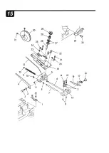
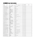
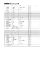
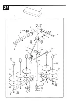
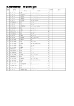
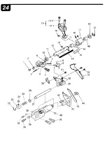
1

311.21-01

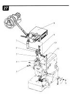
小附件箱

Small attachment box

1

1

2

311.21-02

线架组件

Thread stand,c.set

1

1

3

311.21-02-01

线架上管

Thread Standing Pipe (upper)

(1)

(1)

4

311.21-02-02

线架下管

Thread Standing Pipe (lower)

(1)

(1)

5

201.22-07-09-04

过线臂(长)

Thread Guide Arm (long)

(2)

(2)

202.22-07-09-04

过线臂(短)

Thread Guide Arm (short)

(2)

(2)

6

201.22-07-09-05

张扣

Joint 

(4)

(4)

7

201.22-07-09-06

张扣螺钉

Screw

(4)

(4)

8

201.22-07-09-07

过线磁眼

Thread guide hole

(5)

(5)

9

201.22-07-09-08

螺母

Nut

(4)

(4)

10 201.22-07-09-09

大固定夹螺钉A

Screw

(1)

(1)

11 201.22-07-09-10

固定夹螺钉B

Screw

(3)

(3)

12 201.22-07-09-11

大固定夹

Thread guide holder(large)

(1)

(1)

13 201.22-07-09-12

固定夹连接杆

Thread guide pole

(1)

(1)

14 201.22-07-09-13

螺母

Nut

(7)

(7)

15 201.22-07-09-14

上下管接头

Column pipe connector

(1)

(1)

16 201.22-07-09-15

接头螺钉

Screw

(2)

(2)

17 201.22-07-09-16

穿线杆

Thread guide pole

(1)

(1)

18 201.22-07-09-17

小固定夹

Thread guide holder(small)

(1)

(1)

19 201.22-07-09-18

下管垫片

Washer

(2)

(2)

20 201.22-07-09-19

弹簧垫

Elastic washer

(1)

(1)

21 201.22-07-09-20

大螺母

Nut

(1)

(1)

22 201.22-07-09-21

线圈芯

Spool cushion

(5)

(5)

23 201.22-07-09-22

线圈轴

Spool pin

(5)

(5)

24 201.22-07-09-23

线盘垫

Spool mat

(5)

(5)

25 201.22-07-09-24

线盘

Spool seat disc

(5)

(5)

26 201.22-07-09-25

弹性垫圈

Elastic washer

(5)

(5)

27 201.22-07-09-26

上管盖帽

Column cap

(1)

(1)

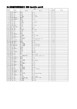
序号

21.附件部分 Ⅱ Accessories part Ⅱ

备注

图号

名称

05M8

1

·

2

Содержание HW762T

Страница 1: ......

Страница 2: ...ontents described in this instruction manual are intended for giving information and subject to change without notice We assume no responsibility for these information and any errors and or incor rect descriptions that may appear in this instruc tion manual eHikari Precise Machinery Science Technology Co Ltd has a policy that we always modify the performance and or specifications of this product i...

Страница 3: ...read and understand very carefully this instruction manualtogether whih that of the driving equipment and take necessary safety measures in order to use this machine effciently and effectively 2 Indications of dangers Warning and cautions To prevent accidents and ensure safety warning indications which show the degree of danger are used on our products and in this manual Study the contents of thes...

Страница 4: ...fl fit I Efli m wm r mEfl ffPJ WmEfl tt ttm f o 2 r fCE j l fu 1f 3t lS I fu 1f 1 fflM1 1ro 3 ffij _fiji_ j1 Sj SjlljE j l fu 1f o 4 jlfj JE j _g t lt1tt 7c ii JJtJLm w QrPJ Etj 1 fu 1f0 5 9 5E ff 1 10 _tE j ff1E J JJJ Etj 1 fu 1f0 6 x tW l1 ffiu itsJJilt _tpfiffi Efl 3 Safety precautions ICDApplication purpose I Our industrial sewing machines have been developed in order to increase quality and o...

Страница 5: ... the machine and users misoperation estabish your oun procedures for safety and follow them 4tAlways turn off the power and unplug the machine before performing the procedures shown below Lubrication Treading Cleaning Replacing the needle Checking replacing the oil element Replacing the oil 4tAlways turn off the power before performing the procedures shown below Adjusting the stitch length Adjusti...

Страница 6: ...ne is packaged in a cardboard box before shipping Unpack your machine in orderly sequence while checking them right side up by referring to the indications such as logo etc printed on the boxes 2 Never hold the area near the needle and or thread guide related parts when taking out the machine from the cushion Otherwise it may cause injury and or damage to the machine 3 Take out the machine very ca...

Страница 7: ...off the oil carefully Fig 3 3 Care should be taken to avoid excessive shock and shake when the machine is mounted on the table and or transferred using a hand truck Otherwise the machine may fall down 4 Wipe off the oil from the machine before packaging it again for secondary transport Otherwise the machine may easily slip out ofyour hands or the bottom of the box may come off while in transit CAU...

Страница 8: ...nnect to another devices 2 Connect the ground wires securely to the indicated ground points on the machine head WARNING I Handing machine oil l Never start the machine with no oil the reservoir Use HIGH SPEED SEWING MACHINE OIL Equivatent of ISO requirements Viscosity index of Vg22 2 If machine oil gets in your eyes it may cause eye irritation To prevent the machine oil from getting in your eyes w...

Страница 9: ...r guard pulley cover etc 2 S Never bring your hands under the needle while running the machine 3 A cluth motor keeps on running for a while after the power is turned off Therefore be careful even after the power is turned off as the machine could start running by pressing the machine treadle 4 S To prevent accidents never bring any part of your fingers hair and clothes near the machine pulley thre...

Страница 10: ...d is installed close to the needle However there is clearance above the finger guard for easy threading Be careful that the needle may penetrate any of your fingers if you insert it into this clearance 3 Pulley Check the direction in which the machine pulley rotates It should rotate clockwise as seen from the pulley 4 Presser foot 9 Never insert any of your fingers There is a clearance of more tha...

Страница 11: ...5 4 25 5 cr I I l I I I I i I I II I I I I I I 4 13 I 300 r 70 038 73 0 2 R10 2 R10 234 409 1 900 8 1 fr1Z 05M8Cw fft JJ7J B Jg i JJ fJUrt i WAa 2 fr1Z 1 UTD lCS1 i WBa oj Q oj l u Q u Q d 00 2 LD oo l I oj c Q 0 bJJ oj d l Q u 0 Q 0 u 0 l 0 till Q Q d Cl I Q I c u Q oj rJl a l Q l c 0 _ _ N 0 z ...

Страница 12: ...ke Fi g 7 Sewing machine installation CAUTION C Alaways tu rn off the power unplug the m achine and then wei lqual ifi ed technicians should instal I the machi ne Operating direction of the machine pulley the machine pulley rotates clockw ise as seen from the end of the mach ine pu I ley Lubrication CAUT ION When lubricating the machine and or replaceing the oil use Pegasus recommended oil Using o...

Страница 13: ...s turn off the power and unplug the machine when you apply oil by hand Apply two or three drops of oil to needle bar 3 by hand when the machine is used for the first time or left unused for some time Fig 9 I HIGH SPEED SEWING MACHINE OIL I 9 Fig 9 5 Checking oil circulation Once the machine has been properly filled with oil press the machine treadle to run the machine and check oil gauge window 4 ...

Страница 14: ...plug the machine when you fill the HR device with silicone oil Fill silicone oil tanks l 2 with silicone oil To prevent thread breakage or fabric damage and the silicone oil before it is too low Fig 11 11 Fig 11 Threading CAUTION Qt Always turn off the power and unplug the machine when you thread the machine l Open eye guard 1 and covers 2 3 and 4 2 Press lever 5 and bracket 6 comes out toward you...

Страница 15: ... t hread and t he t hread being used together to t hread t he m achine B Needle thread Trim t he knots off neatl y before passing t hrough the eye of t he needle to thread C Looper thread Top cover thread Tr im the knots off neatl y af t er passing t hrough t he eye of t he l ooper Be sure to t hread t he m achine correctl y by referring to t he t hreading diagram see page 15 ...

Страница 16: ...cover thread is too loose thread If the top too cover thread the guide by referri ng to line B If the is too tight thread the top cover thread is still too laos thread guide by referring to line the guide by referring to line C 1 k a J Bt 1 1H J Bt 1 ka J BtJtL8 E 7r iJ For more For l ess stretchab For more stretchable thread stretchable threads le threads ...

Страница 17: ... 14 djusting the differential feed ratio l Looaen nut 3 for the differential feed ratio adjustment To increase the differential feed ratio lower lever 4 The finished fabric is shrunk To decrease the differential feed ratio raise lever 4 The finished fabric is stretched 2 After this adjustment tighten nut 3 Fig 15 15 Fig 15 Adjusting stitch length A cAUTION Always turn off the power and unplug the ...

Страница 18: ...fl m m1 JJJE R2 DT iJlll JJJE R3Jtl 1fiJlll o m ey m m o W Efl twiJGT ffl ttEfl k iiAfi o C 17 To t ighten i To toosen 16 Fig 16 Adjusting the thread tension To obtain the proper thread tension adjust need le thread tension knibs 1 top cover thread tension knobs 2 and looper thread tension knob 3 To tighten the thread turn each knob clock wise To loosen the thread turn each knob coun terclockwise ...

Страница 19: ...machine when you clean the machine 1 0pen front cover 4 and slide plate 5 Loosen screws 6 and remove needle plate 7 2 Clean the grooves of the needle plate and the area around the feed dogs 3 Replace needle plate 7 with screws 6 Then close front cover 4 and slide plate 5 Fig 18 18 Fig 18 Replacing the needle LiCAUTION EI Always turn off the power and unplug the machine when you replace the needle ...

Страница 20: ... ffii a j o 8 20 Fig 20 OK NO 0 19 Fig 19 0 i I rep I acement Replace the oil one month after the first use and thereafter every six months If you keep using the old oil it may cause the damage to the machine To drain the o i I l Drain the oil by removing screw 2 on the left side of the oil pan 2 Tighten screw 2 after draining Fig 20 3 As for replenishment of new oil Fig 8 ...

Страница 21: ...hecking and cleaning the oil filter LicAUTION C Always turn off the power unplug the machine and then well qualified technicians should check and clean the oil filter Check and clean the oil filter every six months To check and clean the oil filter l Remove screws 1 and 2 Remove oil reservoir 3 2 Loosen screw 4 Remove inner and outer filters 5 and 6 Then check and or clean these filters 3 Reinstal...

Страница 22: ...7 8 3 8 7 4 5 5 0 17 0 8 1 2 5 000 240 9 3 4 0 4 3 8 3 8 7 4 5 5 0 17 0 8 1 2 5 000 HW762T 05M8 248 8 9 3 6 3 9 8 3 8 7 4 5 5 0 17 0 8 1 2 5 000 356 8 5 3 2 3 5 8 3 8 7 4 5 5 0 17 0 8 1 2 5 000 364 8 1 2 8 3 1 8 3 8 7 4 5 5 0 17 0 8 1 2 5 000 lt f iF l ffilt Comparison table of quivalent s1zes Needle standard B tt Japanese size Organ 9 11 14 16 18 21 ltt German needle Schmetz Nrn 65 75 90 100 110 ...

Страница 23: ...IQL 00 S 2HH3 11111 TEL 00 afl 21 73 1 1 1 1 1 00 8 21 6731131 1 FIJI 00 86 21 87311311 E mall hlkatl chlnahlltarl com ht1p www chlnahlkaii com iltii IJIRfti lt IJfiJ IG n m ntdtl i V tr r l r IF 11 r a lt odf ot llon we r o u fOllh dtanoffltl h nettuwted CE ilt1109001 aDDI lllA IIllJ V HIKARl W t lllM BI l89 fl P OCU _Ofl _ _ COM UTIIIIUD OVIIl OCIC liACH leADER ...

Страница 24: ...preader mechanism 25 26 13 夹线器部分 Thread tension mechanism 27 28 14 挑线 过线器部分 Needle spreader thread handling 29 30 15 打线架部分 Looper thread mechanism 31 32 16 润滑部分Ⅰ Lubrication mechanism Ⅰ 33 34 17 润滑部分Ⅱ Lubrication mechanism Ⅱ 35 36 18 硅油装置部分 H R device and Jacklight 37 38 19 前罩板部分 Front cover parts 39 40 20 附件部分ⅠAccessories parts Ⅰ 41 42 21 附件部分Ⅱ Accessories part Ⅱ 43 44 22 02 型专用件部分 02 Specific pa...

Страница 25: ... 8 J 2 21 11 12 20 19 5 4 18 17 ...

Страница 26: ...rection mark 1 1 10 22 08005000 油封 Oil Seal 1 1 11 01 806000814 1 螺钉 Screw 1 1 12 101 01 13 安全标识 Safety indicating 1 1 13 17 3200500 5 铆钉 Rivet 2 2 14 311 01 08 机型牌 Model Plate 1 313 01 08 机型牌 Model Plate 1 15 311 01 09 油标 Oil sight window 1 1 16 311 01 10G 挡油板 Dust proof cover 1 1 17 01 404000523 1 螺钉 Screw 2 2 18 311 01 11 机壳支柱 Machine frame supporting bar 4 4 19 311 01 12 油网 Oil filter net 1 1 ...

Страница 27: ...II 10 3 11 7 1 23 ...

Страница 28: ...钉 Screw 4 4 16 05 043080900 3 垫片 Washer 6 4 17 311 02 11 挑线护罩Ⅰ Thread takup cover Ⅰ 1 313 02 11 挑线护罩Ⅰ Thread takup cover Ⅰ 1 18 311 02 12 挑线护罩Ⅱ Thread takup cover Ⅱ 1 19 311 02 13 挑线护罩支架 Thread takup cover holder 1 20 01 606001021 1 螺钉 Screw 2 2 21 01 404000623 1 螺钉 Screw 2 2 22 311 02 14 前罩板簧 Positioning spring plate 1 1 23 01 404001623 1 螺钉 Screw 2 2 24 311 02 15 螺钉 Screw 1 1 25 311 02 02 面板堵油螺钉...

Страница 29: ... 11 6 7 11 I I I I J j 1 I 2 __ 1 l I I _ 1 L I _ 1 I 29 6 I I I V28 I o I 12 b L j 6 Ll 25 22 21 13 ...

Страница 30: ...asket 1 1 14 311 03 09 推板 Slip plate 1 1 15 311 03 10 弹簧片 Spring patch 1 1 16 01 404000623 1 螺钉 Screw 2 2 17 311 03 11 弹簧片 Spring patch 1 1 18 01 404001023 1 螺钉 Screw 1 1 19 03 604000320 1 螺母 Nut 1 1 20 22 05004009 防震垫 Cushion 1 1 21 311 03 13 左缝台下罩壳组件 Left cover lower c set 1 313 03 13 左缝台下罩壳组件 Left cover lower c set 1 22 311 03 13 01 左缝台下罩壳 Left cover lower 1 313 03 13 01 左缝台下罩壳 Left cover lower...

Страница 31: ...II 6 18 14 17 10 JO 11 I 10 32 31 I I I I I I 25 26 I I 28 4 29 23 35 34 33 8 I f 21 36 ...

Страница 32: ...ng 1 1 16 01 806750844 1 螺钉 Screw 2 2 17 01 806750514 1 螺钉 Screw 6 6 18 311 04 12 下曲轴左套筒 Bushing 1 1 19 311 04 13 轴承衬套 Bearing Bush 1 1 20 311 04 14 蜗杆 Worm 1 1 21 18 404000823 3 磁钢座螺钉 Screw 1套 1套 22 14 6204 2RS 2 轴承 Bearing 1 1 23 311 04 21G 轴承盖 Bearing cover 1 1 24 01 604000821 1 螺钉 Screw 2 2 25 331 10 03 同步带 Driving belt 1 1 26 331 10 04 01 下轴同步带轮 Lower shaft driving belt wheel c set 1 1 27 331...

Страница 33: ...17 ...

Страница 34: ... 01 404001223 1 螺钉 Screw 2 2 01 435001223 1 螺钉 Screw 2 2 11 311 05 06 挑线球曲柄 Crank 1 1 12 01 506751424 1 螺钉 Screw 1 1 13 311 05 07 上轴配重 Upper shaft counterweight 1 1 14 01 805000514 1 螺钉 Screw 2 2 15 311 04 11 连轴器 Connecting shaft bushing 1 1 16 01 806750514 1 螺钉 Screw 6 6 17 01 806750844 1 螺钉 Screw 2 2 18 311 05 08G 上轴 Upper shaft 1 1 19 14 6204 2RS 1 上轴中 后轴承 Bearing 2 2 20 311 05 09 轴承衬套 Bearing ...

Страница 35: ... 5 4 1 id 23 24 a 17 18 19 1 ...

Страница 36: ...块 Slide block 1 1 11 14 K 8 12 12 滚针轴承 Roller bearing 1 1 12 05 081101603 5 垫圈 Washer 1 1 13 01 404001223 1 螺钉 Screw 2 2 14 01 404001023 1 螺钉 Screw 1 1 15 311 06 12 海棉 Sponge 1 1 16 311 06 13 油毡卡簧 Latch 1 1 17 311 06 14 针杆滑块导轨 Slide block orbit 1 1 18 02 209400921 2 针板螺钉 Screw 2 2 19 311 06 15 针板 Needle plate 1 313 06 15 针板 Needle plate 1 20 311 06 16 针夹 Needle clamp 1 1 21 01 803000314 1 螺钉 Screw...

Страница 37: ... 2 1 4 3 10 11 15 I 13 14 ...

Страница 38: ...50421 1 螺钉 Screw 1 1 8 311 07 04 后护针传动轴 Shaft 1 1 9 05 063101002 1 挡圈 Washer 1 1 10 06 0500611 1 轴用卡簧 Retaining ring 1 1 11 311 07 07 后护针架 Needle guard rear holder 1 1 12 07 0521313 1 垫片 Washer 1 1 13 01 505001024 1 螺钉 Screw 1 1 14 01 504000521 1 螺钉 Screw 1 1 15 311 07 09 后护针挡 Needle guard rear 1 1 16 311 07 10 前护针挡 Needle guard front 1 1 17 01 525000421 1 螺钉 Screw 1 1 备注 05M8 名称 序号 图号 1 2 7 护针传动部...

Страница 39: ...ar 9 1 0 12 14 b 6 ll n 15 1 15 15 2 7 5 24 ...

Страница 40: ...螺钉 Screw 2 2 14 311 08 09 偏心轮 Eccentric wheel 1 313 08 09 偏心轮 Eccentric wheel 1 15 311 08 10 连杆组件 Connecting rod c set 1 1 311 08 10 01 连杆 Connecting rod 1 1 01 404001623 1 螺钉 Screw 2 2 16 311 08 11 连接销 Pin 1 1 8 弯针传动部分 Looper drive mechanism 备注 序号 图号 名称 05M8 1 2 17 05 053101001 5 垫圈 Washer 1 1 18 03 605000400 1 螺母 Nut 1 1 19 311 08 13 弯针组件 Looper 1 1 20 311 08 14 弯针架 Looper holder 1 1 21 01 50500...

Страница 41: ... 8 4 3 21 40 3 54 51 53 46 53 49 50 47 ...

Страница 42: ...1 15 06 0300607 4 开口挡圈 Retaining ring 1 1 16 05 056101000 4 垫片 Washer 1 1 17 12 038180 O型圈 O ring 1 1 18 311 09 15 针距调节按钮弹簧 Spring 1 1 19 311 09 16 针距调节按钮 Pin 1 1 20 311 09 17 送布连杆销 Pin 1 1 21 311 09 18 主轴锁母 Lower crankshaft nut 1 1 22 01 805000514 1 螺钉 Screw 1 1 23 311 09 19 碟形垫圈衬套 Elastic washer space 1 1 24 09 1021020 1 碟形垫圈 Elastic washer 5 5 25 311 09 21 定位螺钉 Screw 1 1 26 311 09 22 送布凸轮座组件 Ec...

Страница 43: ... 1 1 44 311 09 38 差动连杆销轴 Pin 1 1 45 311 09 39 抬牙滑块 Slide block 1 1 46 14 K12 15 10 滚针轴承 Roller bearing 1 1 47 311 09 41 牙叉左下挡板 Differential feed dog holder plate lower 1 1 48 01 404001023 1 螺钉 Screw 2 2 49 311 09 42 牙叉前挡板 Feed dog holder plate front 1 1 50 311 09 43 牙叉油封 Feed dog holder oil seal 2 2 51 311 09 44 差动送布牙 Differential feed dog 1 313 09 44 差动送布牙 Differential feed dog 1 52 311 09 45 主送布...

Страница 44: ......

Страница 45: ...10 03 差动调节杠杆 Differential adjusting lever 1 1 11 22 16506019 橡胶堵 rubber plug 1 1 12 311 10 05 左侧板 Differential adjusting plate 1 1 13 12 078180 O型圈 O ring 1 1 14 311 10 07 差动扭簧 Spring 1 1 15 201 03 08 台螺钉 Screw 1 1 16 01 904000621 1 螺钉 Screw 2 2 17 311 10 08 轴箍 Collar 1 1 18 201 09 24 台螺钉 Screw 1 1 19 311 10 09 差动曲柄 Differential crank 1 1 20 01 505001224 1 螺钉 Screw 1 1 21 311 10 10 差动拨叉 Differenti...

Страница 46: ...17 16 15 14 x 10 20 11 I 19 12 7 28 1 I 1 I 40 i I tr32 6 t j i J I I 5 30 31 4 33 3 1 6 i I i U 34 36 1 2 I v 39 38 ...

Страница 47: ...n rod c set 1 1 311 11 15G 01 拉杆 tension rod 1 1 311 11 15 02 拉杆曲柄 tension rod crank 1 1 311 11 15 03 销轴 Pin 1 1 19 311 11 16 拉杆扭簧 Spring 1 1 20 311 11 17G 拉杆轴固Ⅰ Collar 1 1 21 01 804000614 1 螺钉 Screw 2 2 22 311 11 18G 拉杆轴固Ⅱ Collar 1 1 23 01 804000614 1 螺钉 Screw 1 1 24 311 11 19G 台螺钉 Screw 2 2 25 311 11 20 压脚曲柄拉板 tension board 1 1 26 311 11 21G1 拉杆转块 tension rod block 1 1 27 01 504001421 1 螺钉 Screw...

Страница 48: ...14 13 11 10 7 5 4 2 1 ...

Страница 49: ...driving bar link 1 1 14 311 12 10 喂针连杆 Needle driving lever 1 1 15 01 806750514 1 螺钉 Screw 2 2 16 311 12 11 喂针轴 Needle driving shaft 1 1 17 311 12 12 喂针偏心 Eccentric bushing 1 1 18 01 805000514 1 螺钉 Screw 2 2 19 311 12 13 喂针偏心连杆 Needle driving eccentric link 1 1 12 喂针传动部分 Spreader mechanism 05M8 1 2 备注 图号 序号 名称 20 311 12 14 调节曲柄销 Adjusting crank pin 1 1 21 311 12 15 喂针调节曲柄 Needle driving adjusting ...

Страница 50: ...2 7 3 y 1 4 12 ...

Страница 51: ...Ⅲ 5 5 14 311 13 10 松线板 Tension disk separator 1 1 15 311 13 11 垫片 Washer 5 5 16 311 13 12A 夹线器组件 A Thread tension c set A 3 3 311 13 12B 夹线器组件 B Thread tension c set B 1 1 311 13 12C 夹线器组件 C Thread tension c set C 1 1 17 311 13 12 01 夹线螺钉 Thread tension screw 5 5 18 201 16 02 03 夹线片 Thread tension disk 10 10 19 201 16 02 04 夹线器座 Thread tension base 5 5 20 201 16 02 05A 夹线簧 A Thread tension spring ...

Страница 52: ...24 4 7 1 27 2 20 30 20 31 20 36 26 37 ...

Страница 53: ...der thread handling 序号 23 311 14 11 过线柱 Thread guide 3 3 24 311 14 12 硅油盒过线架 Thread guide 1 1 25 01 503000621 1 螺钉 Screw 2 2 26 05 043080900 4 垫片 Washer 3 3 27 311 14 13 夹线座 Thread tension base 1 1 28 311 14 14 针杆夹线板 A Thread tension plate A 1 1 29 311 14 15 针杆夹线板 B Thread tension plate B 1 1 30 311 14 16 针杆小夹线簧 Thread tension spring 1 1 31 311 14 17 针杆小夹线螺钉 Thread tension screw 1 1 32 311 14 18 喂...

Страница 54: ...r 31 25 26 p f 27 I f ___ 22 21 i 20 32 33 12 10 11 10 8 3 13 1 9 ...

Страница 55: ...15 10 滑动座定位板 Stop plate 1 1 17 311 15 11 滑动座定位扭簧 Spring 1 1 18 311 15 12 台螺钉 Screw 1 1 19 311 15 13 打线架固定板 Bracket 1 1 20 311 15 14 打线架过线Ⅰ Thread guiding part 1 1 21 01 503000421 1 螺钉 Screw 1 1 22 01 104000721 1 螺钉 Screw 2 2 23 311 15 15 打线架过线Ⅱ Thread guiding part 2 2 24 05 027050600 1 垫片 Washer 2 2 25 01 525000421 1 螺钉 Screw 2 2 26 203 19 06 05 压线螺钉 Thread tension screw 1 1 27 203 19 06 06 夹线片 Th...

Страница 56: ...13 t 14 t t 1r _ 11 15 20 24 ...

Страница 57: ...11 311 16 08 喷油嘴组装 distributor 1 1 12 311 16 09 托油盘 Oil receiver 1 1 13 03 604000320 1 螺母 Nut 1 1 14 311 16 10 油管Ⅰ Oil tubeⅠ 1 1 15 311 16 11 油管Ⅱ Oil tubeⅡ 1 1 16 201 14 10 油管单接头 Oil tube joint 2 2 17 311 16 12 油管接头螺钉 Oil tube joint screw 1 1 18 311 11 06 油封 Oil seal 1 1 19 311 16 13 白油管 Oil tube 1 1 20 201 14 12 油管卡簧 Oil tube spring 4 4 21 103 08 36 01 08 卡簧 Oil tube spring 1 1 22 311 16 14 密合垫片 ...

Страница 58: ...5 ...

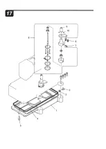
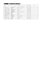
Страница 59: ...01 15 01 03 放油螺钉 Screw 1 1 4 311 17 02 油盘密封圈 Oil reservoir gasket 1 1 5 01 508002024 1 螺钉 Screw 5 5 6 01 505001224 1 螺钉 Screw 2 2 7 201 15 07 油管接头 Oil tube joint 1 1 8 311 17 03 油泵组件 oil pump c set 1 1 9 311 17 03 01 蜗轮 Worm wheel 1 1 10 311 17 03 03 螺钉 Screw 2 2 图号 备注 17 润滑部分 Ⅱ Lubrication mechanism Ⅱ 序号 名称 1 2 05M8 ...

Страница 60: ... 2 I 1 10 12 11 9 i 19 18 17 15 13 ...

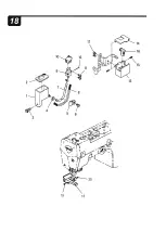
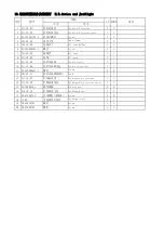
Страница 61: ...5 机针冷却器 Needle cooler 1 1 10 311 18 06 机针冷却器毛毡 Needle cooler felt 1 1 11 01 503000621 1 螺钉 Screw 2 2 12 201 20 13 机针冷却器油线钉 Tack 1 1 13 311 18 07 针线硅油盒 Needlework oil receiver 1 1 14 311 18 08 针线硅油盒盖 Needlework oil receiver cover 1 1 15 15 1200804 1 弹性销轴 Elastic pin 2 2 16 311 18 10 针线润滑毛毡 Needlework felt 1 1 17 20 4350672 4 自攻螺钉 刮削端 Screw 2 2 18 JL 09 节能照明灯组件 Jacklight c set 1 1 19 20 42910723 螺钉 ...

Страница 62: ...1 8 3 9 10 ...

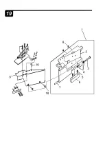
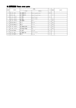
Страница 63: ...3 19 01 01 前罩板 Front cover 1 3 311 19 01 02 销轴螺钉 Bolt 1 1 4 09 0520309 1 垫片 Washer 3 3 5 01 805000614 1 螺钉 Screw 2 2 6 311 19 01 03 前罩板固定块 Hinge 1 1 7 311 03 13 02 罩板连接销轴 Pin 1 1 8 22 05004009 防震垫 Gasket 2 1 9 311 19 02G 前罩板挡板 Cover plate 1 10 01 104000721 1 螺钉 Screw 3 序号 名称 备注 图号 19 前罩板部分 Front cover parts 05M8 1 2 ...

Страница 64: ... 0 7 1 33 11 34 v _10 vg 17 13 21 I 16 2 3 4 5 1 5 2 5 32 31 ...

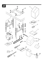
Страница 65: ...n hook 1 1 15 201 22 07 08 13 镊子 Tweezers 1 1 16 201 22 07 08 15 六角扳手 Hexagon Spanner 1 1 17 201 22 07 08 16 有手柄六角扳手 Hexagon Spanner 1 1 18 311 20 11 附件清单 Ⅰ Ⅱ Ⅲ Packing list 1 313 20 11 附件清单 Ⅱ Ⅲ Ⅳ Packing list 1 19 311 20 12 大螺丝刀 Screwdriver 1 1 20 311 20 13 托盘架 Bracket 2 2 21 201 22 07 08 04 台板固定螺套 Nut 4 4 22 311 20 14 垫片 Washer 4 4 23 311 20 15 垫片 Washer 12 12 24 311 20 16 内套 Gasket 4 4 25 311 2...

Страница 66: ...2 ...

Страница 67: ...1 22 07 09 11 大固定夹 Thread guide holder large 1 1 13 201 22 07 09 12 固定夹连接杆 Thread guide pole 1 1 14 201 22 07 09 13 螺母 Nut 7 7 15 201 22 07 09 14 上下管接头 Column pipe connector 1 1 16 201 22 07 09 15 接头螺钉 Screw 2 2 17 201 22 07 09 16 穿线杆 Thread guide pole 1 1 18 201 22 07 09 17 小固定夹 Thread guide holder small 1 1 19 201 22 07 09 18 下管垫片 Washer 2 2 20 201 22 07 09 19 弹簧垫 Elastic washer 1 1 21 201 22 07...

Страница 68: ...fl ...

Страница 69: ...22 06 布条盘组 Tape disc c set 1 15 312 22 06 01 连接杆Ⅰ Pin 3 16 312 22 06 02 托盘 Tope disc 1 17 312 22 06 03 连接块 Thread guide holder 2 18 312 22 06 04 螺钉 Screw 4 19 312 22 06 05 线圈轴 Shaft 2 20 07 0521313 1 垫片 Washer 2 21 03 605000400 4 螺母 Nut 2 22 313 25 05 12 螺钉 Screw 3 23 312 22 06 08 托盘座 Tope disc seat 1 24 01 806000614 1 螺钉 Screw 1 25 312 22 06 10 连接杆Ⅱ Tape disc post 1 26 312 22 06 11 固定夹 Thread gui...

Страница 70: ...fB t ...

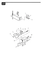
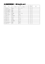
Страница 71: ...1 螺钉 Screw 4 5 313 23 02 前挡板 Front baffle 1 6 01 505001021 1 螺钉 Screw 1 7 313 23 03 拉杆挡板 Bracket 1 8 313 23 04 拉杆Ⅰ Pin Ⅰ 1 9 313 23 05 压板 Stopper 1 10 313 23 06 拉杆Ⅱ Pin Ⅱ 1 11 313 23 07 拉杆弹簧 Spring 1 12 01 805000514 1 螺钉 Screw 1 13 313 23 08 塞子 Washer 1 备注 23 05M8型专用件部分Ⅰ 05M8 Specific partⅠ 05M8 序号 名称 图号 1 2 ...

Страница 72: ...26 25 1 2 4 22 27 38 35 34 6 19 2 19 19 1 20 21 J 14 29 44 43 41 40 ...

Страница 73: ... 4 开口挡圈 Retaining ring 1 22 06 0600812 4 开口挡圈 Retaining ring 1 23 311 10 08 轴箍 Collar 1 24 01 804000414 1 螺钉 Screw 1 25 313 24 13 弹簧 Spring 1 26 05 081101201 5 垫片 Washer 1 27 313 24 15 轴 Shaft 1 28 313 24 16 上刀 Upper knife 1 29 313 24 17 上刀曲柄组件 Upper knife crank c set 1 30 01 806750514 1 螺钉 Screw 1 31 02 508440511 1 螺钉 Screw 1 32 313 24 18 上刀挡板 Chip guard 1 33 01 503000421 1 螺钉 Screw 2 34 313 24 1...

Страница 74: ......

Страница 75: ...Screw 3 3 313 25 02 漏斗固定板 Bracket 1 4 21 3450253 4 螺钉 Screw 4 5 313 25 04 01 漏斗槽上段 Cloth Waste Chute Upper 1 6 313 25 04 02 漏斗槽下段 Cloth Waste Chute Lower 1 7 05 043080900 4 垫片 Washer 4 8 01 404001223 1 螺钉 Screw 4 05M8 备注 序号 图号 名称 25 05M8型专用件部分Ⅲ 05M8 Specific partⅢ 1 2 ...

Страница 76: ...2 3 4 5 6 22 7 8 18 10 11 14 13 ...

Страница 77: ...pring 1 9 01 504000824 1 螺钉 Screw 1 10 313 26 27 摆动座 Sway seat 1 11 313 26 28 轴箍 Collar 2 12 01 804000414 1 螺钉 Screw 3 13 313 26 30 过带架Ⅰ Holder 1 14 313 26 33 过带护套 Jacket 1 15 313 26 26 销轴 Pin 1 16 313 26 25 固定座 Immobility seat 1 17 09 0420408 1 碟形垫片 Washer 2 18 313 26 36 蝶形螺母 Papilionaceous nut 1 19 01 404000823 1 螺钉 Screw 2 20 313 26 37 固定板 plank 1 21 313 26 35 支架 Bracket 1 序号 名称 备注 05M8 26 05M8...

Страница 78: ......

Страница 79: ...7 32 安装座Ⅰ Setting Ⅰ 1 5 313 27 33 安装座Ⅱ Setting Ⅱ 1 6 313 27 34 安装座连接架 Connect rack 1 7 313 27 35 连接杆 Connect pole 1 8 313 27 36 电子橡筋装置 Electric elastic set 1套 9 01 506002024 1 螺钉 Screw 4 10 01 806000814 1 螺钉 Screw 3 11 313 27 37 辅助杆 Auxiliary ship 1 27 05M8型专用件部分Ⅴ 05M8 Specific partⅤ 备注 序号 图号 05M8 名称 1 2 ...

Страница 80: ... 86 21 67311111 ext Foreign Trade Dept t 00 86 21 67311311 Fax 00 86 21 67311311 E mail hikari chinahikari com Http www chinahikari com This manual is only for reference IF there is any modification we apologize for the changing hence caused HW762T 9U Series HIKARl llltn li f ittl i MECHATRONICS LEADING BRAND ihfi ii AUTOMATISM THREAD TRIMMER INSTRUCTION MANUAL PARTS BOOK CE ilu IS09001 2008 L J9i...

Страница 81: ...ting the thread releaser 6 7 6 动作感应器的调整 Adjusting the operation detector 8 7 上装饰线切刀组调整 Adjusting the top cover thread trimmer 9 8 拨线组调整 Adjusting the top cover thread wiper 10 零件手册 PARTS BOOK 1 UT 自动切线机构 一 Thread Trim Mechanism 一 11 12 2 UT 自动切线机构 二 Thread Trim Mechanism 二 13 14 3 拨线机构 Thread Wiper Mechanism 15 16 4 上饰线切线机构 Top Cover Thread Trim Mechanism 17 18 5 抬压脚机构 Foot Lifter Mechanism 19 20 ...

Страница 82: ...1 2 make crank 3 at the same height with the machine frame installed in horiz ontal position as picture 2 Solenoid valve adjusting Remove the rubber plug 4 release nut 5 Adjust nut 6 travel to 17 9mm 3 Solenoid valve fixed position adjusting Adjust solenoid valve face plate 7 crank 3 the A side distance to 117 5mm 将螺母 5 放松时 用扳手调整 弹簧 8 在未固定状态时 请确认曲柄 3 是否能轻轻摇动 Use a wrench to release nut 5 Spring 8 ...

Страница 83: ...ional technicians to adjust the lower knife Please refer to picture install according to order 1 2 After installation confirm by gently shaking rod 3 at the point D 切刀切断动作的确认 请使用一条棉线确认切刀切断的动 作 如切断的效果不好时 请调整弹 簧片 4 Knife to cutting confirm please use the knife to cut off a cotton thread to confirm the action If the effect of cutting is bad please adjust the spring plate 4 ...

Страница 84: ... CAUTION Always turn off the power and ask professional technicians are allowed to adjust the lower knife Please refer picture Connecting rod 1 and Crank 2 with a screw 3 To confirm the size of various parts the highest point of the needle bar 1 Installation state size A is 1mm 2 Adjust the distant please adjust the collar 4 B 2mm 3 Range of movement activities knife 5 Activities knife blade is si...

Страница 85: ... 7mm 4 The entrance of the activities knife should be in the central Of lopper 6 please use screw 7 to adjust and fix 5 Activities knife and fixed knife blade intersec tion size D is 0 5mm Activities knife blade of the vertex size E is 1mm 6 Spring plate back and second hook below under the knife the size F is 0 5 0 7 ...

Страница 86: ...ofessional technicians are allowed to adjust the lower knife 1 The position should be at distance of 167mm which is from holder 1 to the fixed knife 2 The distance between fixed knife blade to the top spring plate 3 is 0 3mm 2 Distance from fixed lever 4 vertex to activities knife 5 knifepoint is 163 5mm And please install when the fixed lever and activities knife is in parallel zTurn the cutter s...

Страница 87: ... machine frame to side of crank cake 2 When screws 4 of the crank 3 is not all the tighten Connect crank 3 after link lever 5 and rank cake 1 fixation 2 When clearance between notch of tension disk separator and tension release shaft is 0 05mm please tighten screws 4 4 Shaft 8 in A size 30mm please tighten screws 9 每条线的张力 与导线架和引线勾的位置有 关 棉线时 请调整为 B 6mm C 7mm D 8 5mm E 6 5mm F 9mm 如使用具有伸 缩性的纱线时 请将上述...

Страница 88: ...影响的位置 使用上装饰线剪线器时 按 G 15mm 进行调 整 Without top cover thread trimmer Position thread releaser10 for top cover thread so that the top cover thread will not be affected if needle and looper threads are loosened With top cover thread trimmer Set G at 15mm ...

Страница 89: ... 5mm 调节好后 请将螺丝 1 拧紧 Adjusting the operation detector CAUTION Always turn off the power and ask professional technicians are allowed to adjust the operation detector Loosen screws 1 Set a clearance of 0 5mm between operation detector 3 and magnet 2 After this adjustment tighten screws 1 ...

Страница 90: ... be careful because the knives easy to your fingers 1 When the needle is at the top turn the journey of the activities knife 1 to the maximum keep it not touching the left needle and spreader 2 So the distance between it and presser foot should keep 2 3mm keep the activities knife can draw the line 2 Adjusting the cutters direction loosen screw 3 of the knife bracket 4 To the right direction After...

Страница 91: ...onal technicians are allowed to adjust the top cover thread wiper When needle is on the top 1 Hight of the top cover thread wiper loosen 2 screw of solenoid bracket 1 The distance of device turns to the maximum the left end Made to tip thread wiper 3 to the lift needle topmost distance about 0 5mm 2 The top cover thread wiper direction The distance between the tip thread wiper and the center line ...

Страница 92: ...34 33 31 1 4 23 9 8 2 13 12 29 20 11 ...

Страница 93: ...ad Trim Mechanism 一 序号 图 号 名 称 备 注 18 361 01 14 辅助夹线弹片 Flat Spring 1 19 361 01 15 夹线弹片 Flat Spring 1 20 01 525000321 1 螺钉 M2 5 2 8 Screw 4 21 05 027050600 1 垫片 Washer 6 22 361 01 16 下切刀固定杆 Lower Knife Holder 1 23 361 01 17 螺钉 M3X2 8 Screw 1 24 361 01 18 垫片 Washer 1 25 361 01 19 下切线刀 Lower Knife 1 26 01 125000621 1 沉头螺钉 M2 5X6 Screw 2 27 361 01 20 拨线板固定架 Thread Takeup Bracket 1 28 361 01 21 拨线板 Thr...

Страница 94: ...22 21 ...

Страница 95: ...id 1 8 01 505001224 1 窝头螺钉 M5 12 Screw 3 9 381 02 04 传动轴 Shaft 1 10 381 02 05 压缩弹簧 Spring 1 11 381 02 06 轴固 Collar 2 12 01 704000611 1 外六角螺钉 M4 6 Screw 3 13 361 02 05 曲柄 Crank 1 14 03 608000520 1 螺母 M8 Nut 1 15 05 053101001 5 垫片 Washer 1 16 03 605000320 1 螺母 M5 Nut 1 17 03 605000461 1 锁紧螺母 M5 Nut 1 18 361 01 04 台阶螺钉 Screw 1 2 UT自动切线机构 二 Thread Trim Mechanism 二 序号 图 号 名 称 备 注 18 361 01 04 台阶螺钉 Scre...

Страница 96: ... 1 13 ...

Страница 97: ... 06 插销 Pin 1 9 06 0300607 4 开口挡圈 Ring 1 10 01 503000521 1 螺钉 M3 5 Screw 1 11 381 03 07 拨线摇臂 Wiper Bar 1 12 381 03 08 拨线钩 Thread Wiper 1 13 381 03 09 夹线弹片 Flat Spring 1 14 05 027050600 1 垫圈 Washer 1 15 01 502000221 1 螺钉 M2 1 7 Screw 1 16 381 03 10 拨线钩导向垫片 Wiper Washer 1 17 01 503000421 1 螺钉 M3 4 Screw 1 18 381 03 11 中继线管夹 Cord Clip 2 3 拨线机构 Thread Wiper Mechanism 序号 图 号 名 称 备 注 数量 18 381 03 11 中继线管...

Страница 98: ... 1 15 ...

Страница 99: ... 12 381 04 11 垫片 Washer 1 13 381 04 09 夹线压力片 Clamp Spring Pressure 2 14 381 04 10 压力调节片 Pressure Adjusting Plate 1 15 01 803000624 1 螺钉 M3 6 Screw 1 16 03 603000250 1 螺母 M3 Nut 1 17 01 525000721 1 螺钉 M2 5 7 Screw 2 18 01 504001024 1 螺钉 M4 10 Screw 2 序号 图 号 名 称 数量 备 注 4 上饰线切线机构 Top Cover Thread Trim Mechanism 18 01 504001024 1 螺钉 M4 10 Screw 2 19 05 043080900 3 垫圈 Washer 6 20 361 04 13G 切刀调整架 Kinfe...

Страница 100: ...1 25 21 20 19 3 18 10 17 13 16 15 17 ...

Страница 101: ... Solenoid 1 4 01 505001224 1 螺钉 M5 12 Screw 3 5 381 05 04 推动块 Pushing Block 1 6 03 610000600 3 螺母 M10 Nut 1 7 01 506001224 1 螺钉 M6 12 Screw 2 8 07 0621320 4 弹性垫片 Washer 2 9 05 062081301 1 垫片 Washer 2 10 01 404000623 1 螺钉 M4 6 Screw 1 11 381 03 11 中继线管夹 Cord Clip 1 5 抬压脚机构 Foot Lifter Mechanism 序号 图 号 名 称 数量 备 注 20 20 ...

Страница 102: ... 1 3 11 19 ...

Страница 103: ...2 12 381 06 06 松线杆传动轴 Thread Guide Shaft 1 13 381 06 07 松线杆固定块Ⅰ Thread Release HolderⅠ 4 14 381 06 08 松线杆固定块Ⅱ Thread Release HolderⅡ 1 15 381 06 09 松线杆 Thread Releaser 6 16 381 06 10 切线用过线板 Thread Guide Plate 1 17 01 404000523 1 十字螺钉 M4 5 Screw 2 18 361 06 04 磁缸座组件 Magnet Bracket 1 6 自动切线松线机构 Thread Releaser Mechanism 序号 图 号 数量 名 称 备 注 18 361 06 04 磁缸座组件 Magnet Bracket 1 19 01 404000823 1 十字螺钉 M4 ...

Страница 104: ...gdl FIOlldJIMilanZone sh8nghal ctlln IIIJIJt 00 21 67311111 TCL 00 86 21 67311111 00 2HI7311311 FIMt 00 2Hl73 1 131 1 E molthii IU la d llnlhlkarl com http www chlnt hlkllri oorn a a fllhl ltlani I M flOt loonr _ ogltoloflho_ _ctuoool ili i 1101001 20ot f Jril liiE I_ HIKARl fia IIJM JIIIIl JfJ1111 FOCVIUte OM HteK UtD 0 IZID O IDIL OOI 11 LEADER ...

Страница 105: ... our product The introduction provides necessary knowledge and notes for using Please read safety introduction carefully and understand them before using The content of the introduction will be amended with the improvement of our product the notice is not announced If you have any doubts or comments about our product and service please contact after sale service ...

Страница 106: ... 4 2 2 停针位的调整 4 2 3 脚踏板后踏力量的调整 5 3 接线与接地 5 3 1 电源线的接法 5 3 2 控制器接线端子图 6 3 2 1 通用型接线端子图 平缝 绷缝和包缝等 5 3 2 2 专用型接线端子图 包缝 含第三光眼功能 6 3 2 3 专用型接线端子图 细嘴包缝 7 4 主控制箱面板操作说明书 8 4 1 主控制箱面板的布局如下示意图 8 4 2 待机状态 8 4 3 缝纫模式及各段针数设置 9 4 4 前固缝方式及针数设置 10 4 5 后固缝方式及针数设置 10 4 6 工艺参数设置 11 4 7 常用参数说明表 13 5 故障码 故障原因 故障排除方法表 15 6 七段数码管显示值与实际数值对照表 16 ...

Страница 107: ...外运作 c 请不要过于接近暖气 电热器 旁运作 d 请保持 30 95 相对湿度 无凝露 1 2 4 请不要在可燃气体或爆炸物附近操作 1 3 安装 1 3 1 控制器请遵照说明书进行正确安装 1 3 2 安装前请先关闭电源并拔掉电源线插头 然后进行安装 1 3 3 装钉电源线时请避免靠近会转动部件 最少要离开 3 公分以上 1 3 4 为防止噪声干扰或触电事故 请将缝纫机 控制箱接地 1 3 5 打开电源之前 确定此供应电压必须符合标示在控制箱铭牌上的指定电压 15 范围内 1 4 保养维修的规定 1 4 1 在操作保养或维修动作前 请先关闭电源 1 4 2 翻抬机头时 与更换机针或梭子或穿线时 请确认电源已关闭 1 4 3 控制箱里面有危险高压电 所以关闭电源后要等 5 分钟以上方可打开控制箱盖 1 4 4 修理及保养的作业 要请经过训练的技术人员执行 1 4 5 不能在电机及控制箱运...

Страница 108: ...正确 1 6 2 缝纫机运转时 请不要去触摸上轮 机针等会动作的部位 1 6 3 所有可动作的部份 必须以所提供的防护装置加以隔离 防止身体接触并请 勿在装置内塞入其它物品 1 6 4 请不要在拆下电机护罩及其它安全装置的情形下操作 1 6 5 不要使电机或控制箱掉在地上 1 6 6 不要让茶水等液态物体流入控制箱或电机内部 2 安装与调整 2 1 控制箱的安装 1 将控制箱及脚踏控速器安装于台板下方 2 将踏板与控速器安装连结 3 安装后示意图 2 2 停针位的调整 2 2 1 松开手轮上的磁钢固定螺丝 调整位置后重新固定 2 2 2 如果实际上停针位超过了预期上针位 将信号磁钢固定盘顺手轮旋转方向调节 反之 逆手轮旋转方向调节 ...

Страница 109: ...5 36 2 3 脚踏板后踏力量的调整 调整需求 调 整 结 果 踏板后踏力量的调整 当螺栓愈向上时 则后踏力量愈重 当螺栓愈向下时 则后踏力量愈轻 3 接线与接地 3 1 电源线的接法 本控制器适用于AC220V单相电源 电压输入范围为铭牌标示电压 15 注意 黄 绿色电源线为接地线 为了人员安全及设备可靠工作 一定要 做好系统的接地工程 ...

Страница 110: ...1 4 5 12 13 6 14 7 1 2 1 大地 2 U相输出 3 V相输出 4 W相输出 2 速度信号 3 立式脚踏剪线控制 4 立式脚踏识别 5 GND 6 GND 7 GND 8 立式脚踏抬压脚控制 9 5V 1 5V 2 安全开关 4 5v 1 针位输出 2 GND 3 GND 4 布边传感器信号 5 GND 6 布边传感器电源 1 30v 2 30v 3 大地 4 30v 5 GND 6 30V PWM 7 GND 8 剪线输出 9 挑线输出 10 30V 11 NC 12 手动到缝开关 13 到缝输出 14 5V照明 1 30V PWM 2 抬压脚输出 1 TXD 2 12V 3 RXD 4 GND ...

Страница 111: ...7 36 3 2 2 专用型接线端子图 包缝 含第三光眼功能 ...

Страница 112: ...8 36 3 2 3 专用型接线端子图 细嘴 ...

Страница 113: ... 十一个 LED 以及十个按 键 面板有待机 缝纫模式设置 前固缝方式设置 后固缝方式设置 工艺参数设置共五种状态 4 2 待机状态 1 上电后 面板显示待机状态 N P F SWM SBM EBM 全熄 各功能键上方的 LED 灯按当前参数值显 示 数码管 T1 T2 显示当前缝纫模式代码 00 自由缝 01 定长缝 02 四段缝 03 七段缝 04 八 段缝 05 W 缝 其余各数码管显示 以当前缝纫模式是自由缝为例 显示如下 2 选择 键 对应的抬压脚 剪线 慢启动 停针位 自动触发等功能将被 设置或取消 同时对应的 LED 点亮或熄灭 ...

Страница 114: ... 显示当前缝纫模式代码 00 自由缝 01 定长缝 02 四段缝 03 七段缝 04 八 段缝 05 W 缝 若为定长缝或多段缝 数码管 T3 显示当前段代号 E F G H 数码管 T5 T6 显示当 前段针数 以四段缝为例 显示如下 若为自由缝 不显示当前缝纫段 缝纫模式及段号针数选择 1 按下 键 数码管 T1T2 可在 00 05 之间循环显示当前缝纫模式 2 按下 键 数码管 T3 可在 E F G H 之间循环显示当前段号 3 按下 或 键 对应的针数加 10 或加 1 0 99 之间循环 键无效 按下 键 返回待机模式 ...

Страница 115: ...显示前固缝方式 0 无前固缝 1 单前固缝 2 双前固缝 3 四 前固缝 T3 T4 分别显示当前的固缝针数 以前双固缝为例 显示如下 按 其上方对应的针数加一 在 0 F 之间循环切换 按 键返回待机状态 4 5 后固缝方式及针数设置 1 在待机状态下 缝纫模式设定状态或后固缝设定状态下 按 键 均可以进入后固缝方式设置状 态 此时 EBM 亮 其余 LED 熄灭 T2 显示当前的后固缝方式 2 按下 键 数码管 T2 循环显示后固缝方式 0 无后固缝 1 单后固缝 2 双后固缝 3 四后 固缝 3 T5 T6 分别显示当前的固缝针数 以后双固缝为例 显示如下 按 其上方对应的针数加一 在 0 F 之间循环切换 按 键返回待机状态 ...

Страница 116: ...数设置状态 数 码管显示密码输入 界面如下图所示 2 按 键 可以输入密码 出厂密码 2222 输入后 按 确认 如果所输入的密码 正确 则进入工艺参数修改状态 显示如下 4 6 2 工艺参数修改 1 在工艺参数设定状态下 键为序号递增键 按该键可进行加 1 操作 序号值 0 99 2 在状工艺参数设定态下 键为序号递减键 按该键可进行减 1 操作 序号值 0 99 3 各键在此状态下为参数设定键 每按一键 参数的对应位加 1 如果加 1 后的参数值 超出该参数的范围则不加 每一个参数设置完后按 键 保存该参数值 再按一次 键返回待机模式 ...

Страница 117: ...PM 自由缝模式时 机头最高转速 P4 定速缝速度 3500 平缝系列 3000 双针系列 200 4000 RPM 定长缝自动触发时的缝纫速度 P5 前固缝速度 1800 200 3000 RPM 执行前固缝时的缝纫速度 P6 后固缝速度 1800 200 3000 RPM 执行后固缝时的缝纫速度 P7 前固缝完暂停 off On off 前固缝完毕暂停 需要踏板触发后 模式才继续运行 P8 后固缝前暂停 off On off 后固缝前暂停 需要踏板触发才执 行后固缝 P9 W 缝速度 1800 200 3000 RPM W 缝模式时的缝纫速度 P15 倒缝最高速度 2500 200 3000 RPM 倒缝时的最高速度 P16 扫线通电时间 50 20 1000 ms 扫线电磁铁的动作时间 P17 暂停过程中按键是否 吸合倒缝电磁铁 on On off 当电机不运转时 按倒缝键是否允 许...

Страница 118: ...f 开启或取消半后踏自动抬压脚 P39 第一针速度限定 3000 200 4000 RPM 第一针缝纫时的速度限定 P40 前固缝补偿参数 1 7 平缝系列 12 双针系列 0 16 前固缝针迹补偿参数 1 P41 前固缝补偿参数 2 5 0 16 前固缝针迹补偿参数 2 P42 后固缝补偿参数 1 7 平缝系列 12 双针系列 0 16 后固缝针迹补偿参数 1 P43 后固缝补偿参数 2 5 0 16 后固缝针迹补偿参数 2 P44 W 缝补偿参数 1 7 平缝系列 12 双针系列 0 16 W 缝针迹补偿参数 1 P45 W 缝补偿参数 2 5 0 16 W 缝针迹补偿参数 2 P46 手动老化开关 0 0 1 0 正常操作模式 1 老化拖车模式 P47 老化停顿时间 2000 100 9999 ms 老化时每次运行之间的时间间隔 P48 老化运行时间 2000 100 9999 ms...

Страница 119: ...时间 P65 布边传感器功能选择 0 0 1 0 无布边传感器 1 有布边传感器 P66 布边传感器类型选择 2 0 3 0 N 输出低有效 1 N 输出高有效 2 P 输出低有效 3 P 输出高有效 P67 布边速度 800 200 5000 RPM 检测到布头信号后的运转速度 P68 全人工后踏剪线 311 311 剪线开启 非 311 剪线关掉 P69 布边延时启动时间 1000 100 9999 ms 检测到布头信号后的延时启动时间 P70 布头针数 10 1 100 布边传感器信号到针孔之间的距离 P71 布尾针数 10 1 100 布边传感器信号到针孔之间的距离 P73 有无布边传感器 off On off 是否有外接布边传感器 P74 倒缝 抬压脚气动选 择 0 0 3 0 全部电动 1 倒缝气动 2 压脚气动 3 全部气动 P76 剪线次数 0 0 9999 每剪一次线计数...

Страница 120: ...下 Err 9 电机过载 1 布料是否太厚 2 机头是否堵住 3 上针位是否正确 有剪线动作的情况下 Err 10 电机超速 1 电机码盘信号丢失 2 光栅信号与电控版本不匹配 Err 11 电机码盘故障 请检查电机码盘线是否松动 Err 12 脚踏脱落故障 请检查脚踏连接线是否松动 Err 13 脚踏上电时被踩下 请检查脚踏是否被卡住 Err 14 电磁铁投入时间过长 1 上针位是否正确 2 布料是否太厚或线太粗导致剪线动作不正常 Err 15 制动回路故障 请检查刹车电阻连接线是否松动 Err 17 电磁铁过流故障 电磁铁故障 请检查电磁铁是否损坏或短路 Err 18 制动回路故障 请检查刹车电阻连接线是否松动 Err 19 21 定位系统故障 电机可继续运转 但无针数记数 针位定位及剪 扫线及倒缝功能 请检查磁钢是否正常 请检查机头是否被卡住 Err 22 上位机通信故障 请检查控制...

Страница 121: ...17 36 6 七段数码管显示值与实际数值对照表 数字部分 实 际 字 符 0 1 2 3 4 5 6 7 8 9 显 示 字 符 英文字符 实 际 字 符 A B C D E F G H I J 显 示 字 符 实 际 字 符 K L M N O P Q R S T 显 示 字 符 实 际 字 符 U V W X Y Z 显 示 字 符 ...

Страница 122: ...map 22 3 2 1 General terminal connection diagram lockstitch interlock and overlock 22 3 2 2 Special terminal connection diagram overlock with the third sensor function 23 3 2 3 Special terminal connection diagram cylinder bed overlock 24 4 Operating description of main control box panel 26 4 1 Layout of main control box panel as follows 25 4 2 Holding state 25 4 3 Sewing mode and each section stit...

Страница 123: ...ng b Avoid exposure to direct sun or outdoors during using c Keep away from the heating heater during using d The relative humidity should be within the range of 30 to 95 1 2 4 Keep away from flammable gases or explosive during using 1 3 Installation 1 3 1 Please install the controller correctly according to the introduction 1 3 2 Please turn off and disconnect the power cord before installation 1...

Страница 124: ...5 Dangerous tips This symbol indicates something you should be careful of when installing failing to follow the instruction could cause injury when using the machine physical damage to equipment and surroundings 1 6 Other safety requirements 1 6 1 Please operate the sewing machine at low speed and check whether the direction of rotation is correct for the first time to power on 1 6 2 Please don t ...

Страница 125: ... 2 1 3 Installation diagram 2 2 Adjustment of needle stop position 2 2 1 Release the magnet fixed screw of the hand wheel re fix after position adjustment 2 2 2 If the actual needle stop position exceed the expected needle up position adjust the magnet fixed plate on the indicative direction of the hand wheel rotation conversely adjust the hand wheel on the reverse direction of hand wheel rotation...

Страница 126: ...olt at down the reverse pressure will be light 3 Connection and grounding 3 1 Connection of power supply The controller is suitable for power supply of AC220V one phase the fluctuation of input voltage is within 15 as the plate marked Notice The yellow green power line are connected to ground the connection to ground must be well done for insurance of safety and devices reliable to work Heeling ba...

Страница 127: ...signal 3 stand foot pedal trimming control 4 stand foot pedal identify 5 GND 6 GND 7 GND 8 stand foot pedal foot presser control 9 5V 1 TXD 2 12V 2 RXD 4 GND 1 NC 2 safety switch 3 NC 4 5v 1 needle position output 2 GND 3 GND 4 cloth edge sensor signal 5 GND 6 cloth edge sensor power 1 30V 2 30V 3 ground 4 30V 5 GND 6 30 PWM 7 GND 8 trimming output 9 thread sweep output 10 30V 11 NC 12 manual reve...

Страница 128: ...24 36 3 2 2 Special terminal connectiondiagram overlock with the third sensor function ...

Страница 129: ...25 36 3 2 3 Special terminal connection diagram cylinder bed overlock ...

Страница 130: ...power on N P F SWM SBM EBM are turned off the LED lamps at the top of function keys display according to the current parameter T1 T2 digital tube display current sewing mode 00 free sewing 01 constant dimension sewing 02 four segment sewing 03 seven segment sewing 04 eight segment sewing 05 W sewing other digital tubes display Take current sewing mode free sewing for example it displays as follows...

Страница 131: ...rrent section code E F G H T5 and T6 digital tube display current section stitch Take four segment sewing for example it displays as follows It doesn t display current sewing section if it is at free sewing Selection of sewing mode section number and stitches 1 Press button T1 T2 digital tube can display circulately current sewing mode among 00 05 2 Press button T3 digital tube can display circula...

Страница 132: ...s Press button the corresponding stitches above added 1 switch circularly among 0 F press button it returns to the holding state 4 5 Back tacking sewing and stitches set 1 Press button at the state of holding sewing mode set or back tacking set it all can go into back tacking mode setting state meanwhile EBM is on other LED is off T2 display current back tacking mode 2 Press button T2 digital tube...

Страница 133: ...ght is on other LED is off it goes into the state of technical parameter setting digital tube display password input as follows 2 Press button it can input password the inital input password is 2222 press to confirm if the entered password is correct then it goes into the state of modifying technical parameter display as follows Back tacking sewing mode Back tacking sewing C Back tacking sewing D ...

Страница 134: ...al slope 20 1 100 The bigger the slope is the larger the low speed region is and the faster the speed change is the smaller the slope is the narrower the low speed region is and the lower the speed change is P1 Speed proportion 8 1 8 Presser proportion of the maximum speed of reverse sewing The maximum seed is equally divided into eight parts current speed can be modified through adjusting parts P...

Страница 135: ...Stitch or speed priority setting during sewing 0 stitch priority 1 speed priority P19 Foot presser switch On On off Turn on off the function of foot presser P21 Selection of counting function 0 0 2 0 Non counting function 1 Bobbin thread counting function 2 Trimming thread counting function P22 Slow startup counting 2 0 15 Stitches when sewing at slow startup speed P23 Slow startup speed 500 200 3...

Страница 136: ...tion parameter 1 P41 Fore tacking sewing compensatio n parameter 2 5 0 16 Fore tacking sewing stitch compensation parameter 2 P42 Back tacking sewing compensatio n parameter 1 7 lockstitch series 12 two needle lockstitch series 0 16 Back tacking sewing stitch compensation parameter 1 P43 Back tacking sewing compensatio n parameter2 5 0 16 Back tacking sewing stitch compensation parameter 2 P44 W s...

Страница 137: ...oot presser when the electromagnet holding on P60 Protection time of foot presser lifting 20 1 120 s Protecting time of foot presser lifting during working P61 Delay time of lifting foot presser 50 20 800 ms How long will it be to start to lift foot presser after the motor stop P62 Delay time of downing foot presser 50 20 800 ms How long is it allowed to startup after foot presser is down P64 Auto...

Страница 138: ...titch foot presser lifting air operated 0 0 3 0 all electric operated 1 reversing air operated 2 presser foot air operated 3 all air operated P76 Number of trimming 0 0 9999 Adding 1 to the counter per trimming clear to zero when the counter is full P77 Control of needle position signal output 0 0 3 0 The output of needle up position is effective at low 1 The output of needle down position is effe...

Страница 139: ...r the motor power cord is off 2 Check whether the machine head is stuck 3 Check whether motor code wheel cord is loose 4 Check whether the needle up position is correct at the case of thread trimming movement Err 9 Motor overload 1 Check whether the fabric is too heavy 2 Check whether the machine head is stuck 3 Check whether the needle up position is correct at the case of thread trimming movemen...

Страница 140: ...ubrication time is up Add the lubrication oil and then recover the operate time of machine head Err 25 Fabric edge sensor error Err 26 Detected cloth when turning on the electricity 1 Take the cloth away and retry 2 The cloth edge sensor setting is wrong reset the type of cloth edge sensor 3 The cloth edge senor is broken If the error still can not be resolve please contact the supplier 6 Table of...

Отзывы: