background image

Network Covert Camera

·

Quick Start Guide


55 

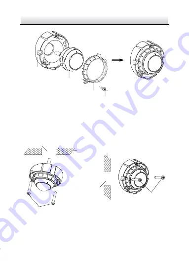
Mounting 

Base

Camera

Fixing Ring

Screw


Figure 2-40


Fix the Camera to Mounting Base 

3.


Install the incline bracket with camera on the wall or ceiling with 
supplied screws. 

Cable Hole

Cable Hole

Ceiling

Wall

Screws

Screws


Figure 2-41


Fix the Camera and Mounting Base to Wall or Ceiling 

4.


Adjust view angle of the camera. Refer to 

Step 5 in Section 2.5.1

Содержание DS-2CD6425G0

Страница 1: ...0 Network Covert Camera Quick Start Guide ...

Страница 2: ...es guarantees or representations express or implied regarding to the Manual About this Manual This Manual is applicable to 64xx Network Camera The Manual includes instructions for using and managing the product Pictures charts images and all other information hereinafter are for description and explanation only The information contained in the Manual is subject to change without notice due to firm...

Страница 3: ...OFITS BUSINESS INTERRUPTION OR LOSS OF DATA OR DOCUMENTATION IN CONNECTION WITH THE USE OF THIS PRODUCT EVEN IF HIKVISION HAS BEEN ADVISED OF THE POSSIBILITY OF SUCH DAMAGES REGARDING TO THE PRODUCT WITH INTERNET ACCESS THE USE OF PRODUCT SHALL BE WHOLLY AT YOUR OWN RISKS HIKVISION SHALL NOT TAKE ANY RESPONSIBILITES FOR ABNORMAL OPERATION PRIVACY LEAKAGE OR OTHER DAMAGES RESULTING FROM CYBER ATTAC...

Страница 4: ...This equipment generates uses and can radiate radio frequency energy and if not installed and used in accordance with the instructions may cause harmful interference to radio communications However there is no guarantee that interference will not occur in a particular installation If this equipment does cause harmful interference to radio or television reception which can be determined by turning ...

Страница 5: ...irective Products marked with this symbol cannot be disposed of as unsorted municipal waste in the European Union For proper recycling return this product to your local supplier upon the purchase of equivalent new equipment or dispose of it at designated collection points For more information see www recyclethis info 2006 66 EC battery directive This product contains a battery that cannot be dispo...

Страница 6: ... any of the warnings are neglected Cautions Injury or equipment damage may occur if any of the cautions are neglected Warnings Proper configuration of all passwords and other security settings is the responsibility of the installer and or end user In the use of the product you must be in strict compliance with the electrical safety regulations of the nation and region Please refer to technical spe...

Страница 7: ...ll be firmly fixed If smoke odor or noise rise from the device turn off the power at once and unplug the power cable and then please contact the service center Cautions Make sure the power supply voltage is correct before using the camera Do not drop the camera or subject it to physical shock Do not touch sensor modules with fingers If cleaning is necessary use clean cloth with a bit of ethanol an...

Страница 8: ...acking of the same texture Regular part replacement a few parts e g electrolytic capacitor of the equipment shall be replaced regularly according to their average enduring time The average time varies because of differences between operating environment and using history so regular checking is recommended for all the users Please contact with your dealer for more details Improper use or replacemen...

Страница 9: ...vert Camera Rear Panel 19 1 3 2 Type II Covert Camera Rear Panel 20 1 3 3 Type III Covert Camera Rear Panel 21 1 4 Sensor Units 22 2 Installation 27 2 1 Installing the Main Unit 27 2 1 1 Installing Type I Covert Camera Unit 27 2 1 2 Installing Type II Covert Camera Unit 29 2 1 3 Installing Type III Covert Camera Unit 30 2 2 Installing the Block Shaped Sensor Unit 32 2 2 1 Concealed Mounting 32 2 2...

Страница 10: ...Network Covert Camera Quick Start Guide 9 2 5 2 Mounting with a Incline Bracket 53 3 Activate and Access Network Camera 57 ...

Страница 11: ... 10 1 Appearance Description 1 1 General Appearance There are two covert camera types the general appearance of the covert camera is shown below 1 1 1 Type I Camera General Appearance 1 2 3 4 5 6 7 Figure 1 1 Type I Camera General Appearance ...

Страница 12: ...1 Main unit 2 Mounting rail 3 Rear panel 4 Front panel 5 POWER Indicator LED Solid red Power on Unlit Power off 6 STATUS Indicator LED Solid green The camera works properly Unlit The camera does not work properly 7 LINK Indicator LED Flashing amber Network properly connected Unlit Network disconnected ...

Страница 13: ... 1 1 2 Type II Camera General Appearance 1 4 3 2 Figure 1 2 Type II Camera General Appearance Table 1 2 Description of the General Appearance No Description 1 Main unit 2 LINK network indicator 3 STATUS status indicator 4 POWER power indicator ...

Страница 14: ...1 2 3 4 Figure 1 3 Type III Camera General Appearance Table 1 3 Description of the General Appearance No Description 1 Main unit 2 POWER Indicator LED Solid red Power on Unlit Power off 3 STATUS Indicator LED Solid green The camera works properly Unlit The camera does not work properly ...

Страница 15: ...Network Covert Camera Quick Start Guide 14 No Description 4 LINK Indicator LED Flashing amber Network properly connected Unlit Network disconnected ...

Страница 16: ...overt Camera Front Panel The Type I covert camera equips with three types of front panel as shown in Figure 1 4 Figure 1 5 and Figure 1 6 AUDIO IN AUDIO OUT VIN1 SD 1 2 3 4 Figure 1 4 The Type A Front Panel AUDIO OUT AUDIO IN VIN1 SD 1 2 3 4 Figure 1 5 The Type B Front Panel ...

Страница 17: ...k Start Guide 16 VIN2 AUDIO IN AUDIO OUT VIN1 SD 1 2 3 4 Figure 1 6 The Type C Front Panel Table 1 4 Description of the Front Panel No Description 1 Audio input 2 Audio output 3 RJ 12 video input interface s 4 MicroSD card slot ...

Страница 18: ...3 Figure 1 7 Type II Camera Front Panel Table 1 5 Description of the Front Panel No Description 1 Power Input 12 V DC 2 Network interface 3 RS 485 connect RS 485 cable ALARM connect OUT and G terminals connect IN and G terminals AUDIO connect OUT and G terminals connect IN and G terminals ...

Страница 19: ...II Covert Camera Front Panel The front panel of the Type III covert camera is shown in Figure 1 8 1 2 3 Figure 1 8 The Type B Front Panel Table 1 6 Description of the Front Panel No Description 1 12 V DC M8 aviation plug 2 LAN interface 3 MicroSD card slot ...

Страница 20: ...covert camera is shown in Figure 1 9 ALARM RS232 RXD TXD GND IN1 1B 1A LAN PoE DC 12V RESET 1 2 3 4 Figure 1 9 Type I Covert Camera Rear Panel Table 1 7 Description of the Type I Covert Camera Rear Panel No Description 1 Reset 2 Power input 3 RS 232 and alarm input and output interfaces 4 Ethernet interface with PoE function ...

Страница 21: ... 1 3 2 Type II Covert Camera Rear Panel The rear panel of the Type II covert camera is shown in Figure 1 10 1 2 3 4 Figure 1 10 Type II Covert Camera Rear Panel 1 RESET button 2 VIN interface Connect SMA Interface 3 USB interface 4 SD card slot ...

Страница 22: ...r panel of the Type III covert camera is shown in Figure 1 11 2 1 3 Figure 1 11 Type II Covert Camera Rear Panel Table 1 8 Description of the Covert Camera Rear Panel No Description 1 Power input 12 VDC AUDIO connect OUT and GND terminals connect IN and GND terminals 2 Reset 3 VIN interface ...

Страница 23: ...ding block shaped sensor unit cylindrical sensor unit tube lens and ball shaped sensor unit Type I Block Shaped Sensor Unit 1 2 3 4 Figure 1 12 Block Shaped Sensor Unit Table 1 9 Description of the Block Shaped Sensor Unit No Description 1 Block Shaped sensor unit 2 Decorative cover 3 Straight mounting bracket 4 Video output cable with RJ 12 interface ...

Страница 24: ...3 Type II Cylindrical Sensor Unit 1 2 3 Figure 1 13 Cylindrical Sensor Unit Table 1 10 Description of the Block Shaped Sensor Unit No Description 1 Cylindrical Sensor Unit 2 Video output cable with RJ 12 interface 3 Round Rail Mounting Bracket ...

Страница 25: ...rt Camera Quick Start Guide 24 Type III Tube Lens 1 2 3 Figure 1 14 Tube Lens Table 1 11 Description of the Tube Lens No Description 1 Tube Lens 2 Ceiling Mounting Bracket 3 Video output cable with RJ 12 interface ...

Страница 26: ...ype IV Ball Shaped Sensor Unit The ball shaped sensor unit has two models with different communication interfaces the RJ 12 interface and M12 interface RJ 12 Interface M12 Interface 1 2 3 4 Figure 1 15 Ball Shaped Sensor Unit and Included Bracket ...

Страница 27: ...mera Quick Start Guide 26 Table 1 12 Description of Ball Shaped Sensor Unit No Description 1 Ball Shaped Sensor Unit 2 Video output cable with RJ 12 interface 3 Video out cable with M12 aviation plug 4 Bracket Included ...

Страница 28: ...he products for the installation environment Make sure that the wall is strong enough to withstand four times the weight of the camera and the bracket For the camera that supports IR you are required to pay attention to the following precautions to prevent IR reflection Make sure that there is no reflective surface too close to the camera lens The IR light from the camera may reflect back into the...

Страница 29: ... Secure the bracket on the rear surface of the main unit with corresponding screws Figure 2 2 Secure Bracket onto Main Unit Do not upside down the main unit when you fasten the bracket Hang the main unit together with the bracket to the mounting rail and complete the installation ...

Страница 30: ...in Unit 2 1 2 Installing Type II Covert Camera Unit Steps 1 Secure the mounting rail onto the installation surface with the supplied PA3 25 screws Figure 2 4 Secure the Mounting Rail 2 Secure the bracket on the rear surface of the main unit with corresponding screws ...

Страница 31: ... not upside down the main unit when you fasten the bracket 3 Hang the main unit together with the bracket to the mounting rail and complete the installation 2 1 3 Installing Type III Covert Camera Unit Steps 1 Secure the bracket on the rear surface of the main unit with four M2 5 screws ...

Страница 32: ...k Covert Camera Quick Start Guide 31 Main Unit Bracket Figure 2 6 Secure Bracket onto Main Unit 2 Secure the bracket onto the installation surface with the supplied screws Figure 2 7 Secure the Mounting Rail ...

Страница 33: ... cover 2 2 1 Concealed Mounting Please make sure that the mounting surface is suitable for adhesive pasting Steps 1 Drill on the mounting surface as shown in Figure 2 8 Drill on the Surface Make sure the drilling hole is big enough for the camera lens 2 Remove a side of the adhesive tape on the bracket Paste the bracket on mounting surface by aligning with the drilled hole ...

Страница 34: ...amera Quick Start Guide 33 Paste the Bracket 3 Install the block shaped sensor unit into the bracket and make it to be buckled 4 Tighten the fastening screw on the top of the bracket Insert the Block shaped Sensor Unit ...

Страница 35: ...ock shaped sensor unit on the mounting surface with screws as shown in Figure 2 11 Fix the Block shaped Sensor Unit For cement surface mounting you need to use the expansion screw to fix the camera For wooden surface mounting you can just use the self tapping screw to fix the camera ...

Страница 36: ...corative cover As shown in Figure 2 12 Hood the Cover 2 2 3 Mounting with Pole Shaped Bracket If you purchase the camera with a pole shaped mounting bracket follow the steps to complete installation of the lens and the bracket Lens Bracket Cover Base Pole Shaped Bracket Component ...

Страница 37: ...bracket as shown below Lens Lens Bracket Cable Fit Lens and Lens Cable into Lens Bracket 2 Make a mark at a height of 1 83m 6ft on wall or other desired mounting position Align the 1 83m 6ft sticker on base with the mark on wall Then mark the first expansion screw hole as shown in the figure below ...

Страница 38: ...Network Covert Camera Quick Start Guide 37 1 83m 6ft 1 83m 6ft 1 83m 6ft Marking for Installation 3 Install the first expansion screw loosely and hang the bracket base on the screw ...

Страница 39: ...ket supports cable routing through wall and on surface select one way according to your actual needs 1 If you choose to route cable through wall drill a cable hole according to the size and height of cable hole on the base See Figure 2 17 2 If you choose to route cable on surface make a cable hole on the top or bottom cover See Figure 2 17 ...

Страница 40: ...ick Start Guide 39 1 83m 6ft Cable Holes Cable Hole Route cable through wall Route cable on surface Plan Cable Routing 5 Route cable and fit the lens bracket into the base Use a screw to secure the lens bracket See Figure 2 18 ...

Страница 41: ...Start Guide 40 or Install and Secure Lens Bracket 6 Loosely screw the thumbscrew to the base Adjust the panning position of the lens and tighten the thumbscrew Thumbscrew Pan 15 to 15 Install Thumbscrew and Adjust Panning Position ...

Страница 42: ...to the base 1 83m 6ft 1 83m 6ft Top Cover Install Top Cover 8 Install the second expansion screw Tighten the first expansion screw See Figure 2 21 9 Peel off protective films on both side of the decorative cover Slide the decorative cover in the base See Figure 2 22 ...

Страница 43: ...overt Camera Quick Start Guide 42 1 83m 6ft First Expansion Screw Second Expansion Screw Secure Base on Wall Decorative Cover Protective Films Peel off Protective Films and Slide the Decorative Cover in the Base ...

Страница 44: ...the base Bottom Cover Install Bottom Cover Installing the Cylindrical Sensor Unit This series of camera only support concealed mounting Please make sure that the mounting surface is suitable for adhesive pasting Steps 1 Drill on the mounting surface as shown in Figure 2 24 ...

Страница 45: ...hole is big enough for the camera lens 2 Remove a side of the adhesive tape on the bracket Paste the bracket on the mounting surface with aligning with the drilling hole As shown in figure below Paste the Bracket 3 Install the cylindrical sensor into the mounting hole in the round rail bracket ...

Страница 46: ...tart Guide 45 4 Turn the locking sleeve to fix the sensor Install the Cylindrical Sensor Installing the Tube Lens Steps 1 Fix the mounting base of the bracket to the ceiling with the supplied screws Fix the Ceiling Mounting Bracket ...

Страница 47: ...Network Covert Camera Quick Start Guide 46 2 Hood the bracket cover to the mounting base Hood the Bracket Cover 3 Screw the bracket to the mounting base Screw the Bracket ...

Страница 48: ... please select the bracket according to your demand 4 Loop the tube lens with the loop of the bracket and tighten it with the supplied screw As shown in Figure 2 30 Loop the Tube Lens 5 Align the assembled tube lens to the bracket and rotate the lens to tighten the lens with the bracket ...

Страница 49: ...a Quick Start Guide 48 Install the Tube Lens to the Bracket 6 Loosen the knob to adjust the surveillance angle and then tighten the lock nut to complete the installation Knob Lock Nut Figure 2 32 Complete the Installation ...

Страница 50: ...Included Bracket Steps 1 Paste the drill template to the desired mounting place Drill two screw holes and a hole for routing cable according to the drill template Figure 2 33 Drill Template 2 Route the camera cable through the mounting base of the included bracket Fixed the mounting base to the wall or ceiling ...

Страница 51: ...rews Mounting Base Ceiling Cable Hole Screws Mounting Base Cable Hole Wall Figure 2 34 Fix the Mounting Bracket on Ceiling or on Wall 3 Place the camera in the bracket cover Screw Bracket Cover Camera Figure 2 35 Place the Camera in Bracket Cover ...

Страница 52: ... the wedge on the bracket cover stuck in the slot of the mounting base close the cover and screw the bracket cover on the mounting base loosely Slot Wedge Camera Bracket Cover Mounting Base Screw Hole Figure 2 36 Install the Camera and Bracket Cover ...

Страница 53: ...g tilting and rotating position to desired place Plastic Ring Camera Tilt 16 5 to 16 5 or 21 5 to 21 5 Pan 16 5 to 16 5 or 21 5 to 21 5 Notch Notch Rotate 0 to 360 Figure 2 37 Adjust the View Angle 6 Remove the plastic ring after adjustment finished For the camera equipped with a fisheye lens the panning and tilting adjusting range is 16 5 to 16 5 For the camera equiped with a regular fixed focal ...

Страница 54: ...a Incline Bracket Before you start There is no incline bracket included in the package If you choose this mounting type you need to provide a bracket before starting The shown bracket below is only for demonstration Steps 1 Paste the drill template to the desired mounting place Drill two screw holes and a hole for routing cable according to the drill template ...

Страница 55: ...e 2 39 Drill Template 2 Route the camera cable through the mounting base of the incline bracket And fix the camera to the mounting base with the fixing ring and screw The screw should be installed loosely to leave some space for view angle adjustment ...

Страница 56: ...ix the Camera to Mounting Base 3 Install the incline bracket with camera on the wall or ceiling with supplied screws Cable Hole Cable Hole Ceiling Wall Screws Screws Figure 2 41 Fix the Camera and Mounting Base to Wall or Ceiling 4 Adjust view angle of the camera Refer to Step 5 in Section 2 5 1 ...

Страница 57: ... Quick Start Guide 56 5 Tighten the screw on fixing ring 6 Install the incline bracket cover Mounting Base Incline Bracket Cover Ceiling Mounting Base Incline Bracket Cover Wall Figure 2 42 Install the Incline Bracket Cover ...

Страница 58: ...Network Covert Camera Quick Start Guide 57 3 Activate and Access Network Camera Scan the QR code to get Activate and Access Camera Note that mobile data charges may apply if Wi Fi is unavailable ...

Страница 59: ...0 UD09899B 0505001080816 ...

Отзывы: