background image

O P E R A T O R   M A N U A L  


18 

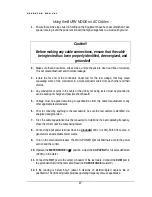
Capacitance 

Frequency 

5

µ

F or less 

.1 Hz 

10

µ

F or less 

.05Hz 

25

µ

F or less 

.02Hz 

50 

µ

F or less 

.01Hz 


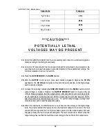
* * * C A U T I O N * * *  

P O T E N T I A L LY   L E T H A L  

V O LTA G E S   M AY   B E   P R E S E N T  


13.


Uncoil the GROUND CABLE from the reel assembly and connect to a solid station ground. 

Clamp securely to the trolley ground clamp.  

14.


Uncoil the HV Output cable from the reel and connect the output lead to the test sample. Be 

sure that there is enough clearance to grounded objects for the expected test voltage. The 

minimum clearance in air is 10 kV ac/inch.   

15.


Place the OUTPUT MODE in the BURN position 

16.


With the OUTPUT  control at zero  (zero start interlock engaged), depress the HV ON 

pushbutton. The HV ON light will glow. At this time the pump and fan on the high voltage 

section will also energize.  

17.


Increase the output by operating the HIGH VOLTAGE control to the RAISE position until full 

output voltage is reached. Observe the OUTPUT  PERCENT  meter to rough in the set 

voltage. Please recognize that the output cycle is: 100 seconds for a full sine wave @.01 

Hz, 50 seconds fro a full sine wave @ .02 Hz, 20 seconds for a full sine wave @ .05 Hz, 

and 10 seconds for a full sine wave @ .1 Hz. . To set the output voltage you may need 

more than one cycle to read the output accurately.  

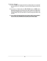
18.


When the load faults, the BURN reactor is switched into the primary of the high voltage 

tank. This reactor will limit the fault current to the maximum rating for the test set. The fault 

current will flow only while the VLF output is above ground. As the output reaches zero and 

changes polarity, the fault current will extinguish. The fault current will re-initiate when the 

output voltage has reached the fault break-over voltage in the next half of the output wave. 

Содержание VLF Series

Страница 1: ... source The operator of this equipment must use good judgement and follow all safety precautions noted in this guide to ensure the protection of himself and others in close proximity to the test area Failure to follow the instructions could result in injury or death Proper grounding of the test set must be done prior to connecting this unit to a power source saMine VLF 50CMF SERIES Please Refer to...

Страница 2: ...VLFOperatorManual HIGH VOLTAGE INC 31 Route 7A Copake N Y 12516 Phone 518 329 3275 Fax 518 329 3271 http www hvinc com E mail factory hvinc com ...

Страница 3: ... the VLF test set measures the Peak voltage It is the peak output voltage that is used during VLF testing If your test specification indicates a test voltage in RMS multiply by 1 414 to obtain the peak value for the test The IEEE400 2 chart indicating test voltages for different cable ratings shows both rms and peak All other AC hipoting using 50 60 Hz instruments is measured by the rms voltage no...

Страница 4: ...ons 6 Controls and Indicators 7 9 List of Components 10 S E C T I O N 2 Setting up the Equipment 11 12 Typical VLF Connection Scheme 13 Operating the Equipment 14 19 VLF Cable Testing Recommendations 20 21 Blank Page for Notes 22 S E C T I O N 3 Performing Special Operations 23 Voltmeter Re calibration 23 24 Current Meter Re calibration 24 Weekly Maintenance 24 Yearly Maintenance 25 Return Materia...

Страница 5: ...customer s established procedures for the use of this type of equipment This Operator Manual is organized to provide information on the VLF 50CMF in steps that familiarize the new operator with the entire scope of operation of this test set Section 1 Specifications and Controls Section 2 Setup and Operation Section 3 Performing Special Operations TheFunctions Features andSpecifications oftheVLFSer...

Страница 6: ...5 02 and 01Hz frequencies standard Continuously adjustable output voltage Continuous duty rating Fixed primary overload Zero Start and External Interlock provision Single range voltmeter Single range current meter with capacitance measuring scale for determining best test frequency Dual operating mode Hipot Burn for either hipotting with an overload or burning with current limiting Three piece des...

Страница 7: ...Hook with 20ft lead WARNING DO NOT OPERATE THE VLF HIPOT SET IF THE HIGH VOLTAGE TANK IS 5 OR MORE FROM LEVEL IF THE UNIT IS OPERATED OUT OF LEVEL OVERHEATING AND INTERNAL ARCING MAY OCCUR DO NOT STORE OR TRANSPORT VLF HIGH VOLTAGE SECTION ON IT S SIDE ...

Страница 8: ...ating Temperature 5 C to 45 C 22 F to 113 F Output power is de rated linearly by 15 from 30 to 45 C ambient Maximum Relative Humidity 80 up to 31 C 88 F decreasing linearly to 50 at 40 C 104 F Mains supply fluctuation 10 of rated voltage Installation Category II Pollution Degree 2 WARNING DO NOT OPERATE THE VLF HIPOT SET IF THE HIGH VOLTAGE TANK IS 5 OR MORE FROM LEVEL IF THE UNIT IS OPERATED OUT ...

Страница 9: ...O P E R A T O R M A N U A L 5 Safety Symbol Identification Warning Please refer to documentation before operation Protective Earth Terminal Warning Hazardous Voltage ...

Страница 10: ... 50 0µF 01 Hz Minimum capacitance to achieve full output 01µF Kilovoltmeter 3 5 in 0 60 PEAK KILOVOLTS 2 FS Accuracy Current Meter 3 5 in 0 200 MILLIAMPERES 6 0uF 5 FS Accuracy Remote Control Size Power Section Size High Voltage Tank size Complete Trolley 17 w x 11 d x 9 5 high 20lbs 20 w x 14 d x 27 high 160lbs 13 5 w x 19 d x 23 high 310lbs 28 w x 60 d x 51 high Complete Trolley 775 lbs 352kg In...

Страница 11: ...R N A L I N T E R L O C K The Ext Intlk connector is provided to allow for a normally open safety interlock switch to control the energizing of the high voltage output F A U L T R E S E T The FAULT RESET pushbutton illuminates when the primary current in the power section has exceeded the maximum limit Its delayed trip allows for the short term overload of the variable transformer while still prov...

Страница 12: ...harge and discharge currents in the cable load 1 precision resistors minimize the need for re calibration due to aging shift The CAPACITANCE scale on this meter is for measuring the load cable capacitance prior to test to determine the best operating frequency for that particular cable run S C O P E O U P U T The SCOPE OUTPUT allows for accurate output voltage monitoring This connector can be fed ...

Страница 13: ...ing circuit for capacitance measuring or for output current measurement C A P A C I T A N C E P U S H T O R E A D X 1 P U S H B U T T O N The PUSH TO READ X1 pushbutton changes the scale of the CAPACITANCE metering The modified Wheatstone Bridge incorporated in this circuit indicates x10 readings without depressing the PUSH TO READ X1 pushbutton When in the x10 scale and the reading is below 6 µF ...

Страница 14: ...Intlk jumper plug 10 ft interconnect cable with grounds power section to HV tank 20 ft interconnect cable power section to control box 6 ft BNC to BNC coax cable scope to panel interconnect 20 ft red and black test leads for capacitance measurement Safety Ground Hook with 20 ft lead ...

Страница 15: ...e 1 Be sure that all the controls are off in their de energized or fully counterclockwise position 2 Secure ground leads to the high voltage tank brass stud and the power section brass stud The Ground leads should be of sufficient ampacity to carry any expected fault currents from the load cable 3 Secure the interconnect cables from the power section to both the control and the high voltage tank T...

Страница 16: ...the START TIMER pushbutton The timing function will count up to the preset value Upon reaching the dwell time an alarm will sound indicating the need to return the Output Control to zero and turn off the high voltage as noted in the Operating Manual by allowing the output discharge solenoids and polarity solenoids to cycle at least ten more seconds one full cycle The timer supplied will be settabl...

Страница 17: ...O P E R A T O R M A N U A L 13 ...

Страница 18: ...n Testing 1 Ensure that all the steps listed in Setting up the Equipment have been accomplished Take special note to ground the power section and the high voltage tank to a solid earth ground Caution Before making any cable connections ensure that the cable being tested has been properly identified de energized and grounded 2 Make sure that all insulators stress cones and pot heads are clean and f...

Страница 19: ...on x10 multiplier depress the x1 pushbutton Then following table provides operating frequency versus capacitance Capacitance Frequency 5µF or less 1 Hz 10µF or less 05Hz 25µF or less 02Hz 50 µF or less 01Hz 13 An oscilloscope optional can be connected to the SCOPE OUTPUT on the control for wave shape monitoring The oscilloscope should be properly grounded and the input should be set to 1 volt divi...

Страница 20: ...u may need more than one cycle to read the output accurately 19 Maintain the output voltage for the test time specified in your standard procedures 20 After the test is complete depress the HIGH VOLTAGE control in LOWER position allowing the load to return to zero and the unit to cycle for about 60 more seconds prior to depressing the HV OFF pushbutton Allowing the unit to cycle for some time allo...

Страница 21: ...azard 5 Voltage must be applied according to specifications from the cable manufacturer or any other applicable test standards 6 Prior to connecting anything to the test sample be sure the test sample is identified de energized and grounded 7 First the cable capacitance must be measured to determine the best operating frequency Place the control near the cable being tested 8 Connect the input powe...

Страница 22: ...igh voltage section will also energize 17 Increase the output by operating the HIGH VOLTAGE control to the RAISE position until full output voltage is reached Observe the OUTPUT PERCENT meter to rough in the set voltage Please recognize that the output cycle is 100 seconds for a full sine wave 01 Hz 50 seconds fro a full sine wave 02 Hz 20 seconds for a full sine wave 05 Hz and 10 seconds for a fu...

Страница 23: ...TAGE control in LOWER position allowing the load to return to zero and the unit to cycle for about 3 more cycles prior to depressing the HV OFF pushbutton Allowing the unit to cycle for some time allows for the complete discharge of the load and avoiding the normal self recharge that capacitive loads will exhibit 21 Prior to removing the output cable from the load observe that the output voltmeter...

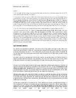
Страница 24: ... testing time durations have been established for the two most commonly used test signals the cosine rectangular and the sinusoidal wave shapes The voltage levels installation and acceptance are based on most used practices world wide of between 2 Uo and 3 Uo where Uo is the rated voltage for cables rated between 5 kV and 35 kV The maintenance test level is about 80 of the Acceptance test level On...

Страница 25: ...at the great majority of defects were grown to failure and be willing to live with a 2 3 in service failure rate over the next few years on cables that passed the VLF test Even at 3 the in service failure rate would be less by multiples than if the cable was never tested or tested with DC voltage In addition to the years of European and North American research an extensive review of VLF testing pe...

Страница 26: ...O P E R A T O R M A N U A L 22 THIS PAGE LEFT BLANK FOR APPLICATION NOTES ...

Страница 27: ... the meter The certification of meters on a yearly basis is recommended to ensure accurate test results Voltmeter Re calibration 1 Locate the unit in a position that will allow easy reading of the meters 2 Remove the panel screws and support the panel vertically to gain access to the calibration pot on the back of the voltmeter 3 Zero the meter movement using the zero adjustment below the scale wi...

Страница 28: ...he output current to one half scale on the unit meter Adjust R6 located on the base of the control as required 7 Check calibration at both half and full scale If the customer facility calibration certification requires more points of reference follow those procedures instead of these Oil Insulated High Voltage Tanks The oil filled tanks in all the VLF SERIES of hipots are field serviceable The onl...

Страница 29: ...heir particular needs The typical required yearly maintenance items are 1 Calibration verification 2 Thorough cleaning of the control and cooling section of the high voltage tank 3 Replacing the HV insulating oil if necessary Approximately every 2000 hours of use 4 Replacing the oil filter if necessary Approximately every 2000 hours of use ...

Страница 30: ... if the return of the equipment is appropriate If deemed appropriate a Return Authorization Number will be issued At that time the Purchaser will be instructed how to mark and return the equipment The above procedure must be adhered to in order to ensure prompt service No equipment should be returned without the prior knowledge and authorization of High Voltage Inc REPLACEMENT PARTS ORDERING To or...

Страница 31: ...t in cash before shipment of goods c If Purchaser so requests and makes arrangements prior to shipment which meet High Voltage s full satisfaction High Voltage in its discretion may accept irrevocable letters of credit in its favor issued by a United States bank which is satisfactory to High Voltage 7 INFRINGEMENT ETC On goods manufactured to Purchaser s specifications Purchaser shall and does ind...

Страница 32: ...that this document is voidable or void shall be submitted to final and binding arbitration before and in accordance with the Commercial Rules of the American Arbitration Association then in effect and judgment upon the award may be entered in any court have jurisdiction thereof provided however that this clause shall not be construed to limit any rights which High Voltage may have to apply to any ...

Страница 33: ...ve 0 1 0 02 Hz to 2 75 uF 30 kVac 0 4 uF VLF Withstand VLF TD VLF PD VLF TD Pair VLF VLF Diagnostic Cable Testing Tan Delta Partial Discharge HV Dividers 150 kV AC DC 300 kV AC DC VLF Thumper 0 9 18 36 kV 3200J 400mA Burny TDR Radar TD 34E 0 34 kV TDB 60 0 60 kVac Capacitor Discharge Systems Thumpers Three Full Joule Outputs VLF Thumper Combo PRODUCT SUMMARY 100 kVac 10 kVA PD 10 pc Concentric Neu...

Отзывы: