Hi-Force HPF Series Скачать руководство пользователя страница 8

Operating Instruction Manual: 

OM-HPF PUMP-01 

From Serial Number: 

BS8412 


5.0 Installation/Setup 


5.1 Before First Use 


1.  Immediately after unpacking, examine the pump for signs of transit damage and if found contact the 

shipping company. 

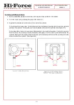
2.  Remove the temporary transit fitting / plate which is fitted in the position of the oil filler breather cap 

(7) and fit the oil filler breather cap which is packed separately. 

3.  Establish  the  oil  level  in  the  oil  reservoir  using  the  level  gauges  (8).  Depending  on  the  shipping 

method used, the reservoir may either be supplied full or empty. If the reservoir is empty, it must be 
correctly filled before use (See section 5.2).  If the pump was supplied full of oil, no further action is 
required.  


IMPORTANT:

 Running the pump without oil will result in damage.


CAUTION:

 Ensure the oil level does not fall below the minimum level as shown by the level gauge 

(8) or the oil level on the dipstick (7) measures more than 180mm from the underside 
of the filler breather cap (7).


4.  Ensure the lever of the hydraulic directional control valve (3) is set to the neutral position: This is 

fully anti-clockwise for models with a 2-way valve, or the central position for models with a 3-way or  
4-way valve.  

5.  Make sure that the voltage indicated on the motor rating plate corresponds with the available supply.  

6.  Connect the motor to required power source. (See section 5.3) 

7. 

Check the direction of rotation of the motor by pressing the green ‘ON’ button (1), then immediately 
pressing the red ‘OFF’ button. While doing this observe the motor fan. The motor should run in a 
clockwise direction when viewed from above. If the motor turns anti-clockwise, check the wiring of 
the electrical connector. 

CAUTION:


Running the pump with the motor turning in the incorrect direction may damage the low-
pressure pump unit. 

8.  The pump is fitted with an adjustable pressure relief valve (5) to restrict the output capacity to any 

desired value, up to the maximum working capacity of the press. (See section 6.1) 


Содержание HPF Series

Страница 1: ...e at the time of publication and approval Hi Force reserves the right to make changes to this document at any time without notice This original instructions document assumes that the operator carrying out any operation with this product is trained and competent to do so This manual does not attempt to cover all details or variations in the equipment Nor does this manual claim to provide for every ...

Страница 2: ...ty 5 4 0 Component Identification 6 5 0 Installation Setup 8 5 1 Before First Use 8 5 2 Filling the Pump with Oil 9 5 3 Electrical Connection 9 5 4 Bleeding Trapped Air from the System 9 6 0 Operation 10 6 1 Setting the Press Operating Capacity 10 6 2 Pumps with Manual Valves 11 6 3 Pumps with Solenoid Valves 12 7 0 Maintenance 12 8 0 Specifications 13 8 1 HPF Pump Specifications 13 8 2 HPF Pump E...

Страница 3: ...tor who can offer training courses for operators 2 2 Work Area Safety Keep work areas clean and well lit Cluttered spaces and inadequate lighting can result in unnecessary accidents Keep unauthorised persons at a safe distance from the task site NEVER use the tools in the presence of inflammable liquids gases or material DO NOT use the tools in potentially explosive atmospheres ATEX this tool is N...

Страница 4: ...pler check valve that is under pressure Doing so could result in the sudden uncontrolled release of hydraulic oil at high pressure which could cause significant injury or death Immediately replace any worn or damaged parts using genuine Hi Force parts only DO NOT remove any labels from the product Replace any damaged or unreadable label immediately Failure to observe and obey the following safety ...

Страница 5: ...t a cylinder tool with a lower pressure capacity rating to any Hi Force pump of this model series This pump is not suitable for work which takes place in explosive environments Failure to observe and obey the following safety precautions could result in property damage equipment damage or minor moderate personal injury ALWAYS stand the pump on a stable level surface during operation BEWARE of hot ...

Страница 6: ...Gauge 2 Hydraulic Service Connections 9 Hydraulic Oil Drain Plug 3 Directional Control Valve 4 Motor 5 Adjustable Pressure Relief Valve 6 Oil Reservoir 7 Oil Filler Breather Cap with Dipstick One or two ports depending on valve type If fitted Type will vary Motors will vary depending on supply requirements Figure 4 1 Component Identification ...

Страница 7: ...Operating Instruction Manual OM HPF PUMP 01 From Serial Number BS8412 7 Figure 4 2 Component Identification ...

Страница 8: ... level on the dipstick 7 measures more than 180mm from the underside of the filler breather cap 7 4 Ensure the lever of the hydraulic directional control valve 3 is set to the neutral position This is fully anti clockwise for models with a 2 way valve or the central position for models with a 3 way or 4 way valve 5 Make sure that the voltage indicated on the motor rating plate corresponds with the...

Страница 9: ...try to country Hi Force pumps will operate within the normal voltage tolerance ranges but in extreme cases where they are operated for long periods at high pressures and in low voltage conditions the motor may overheat and shut down NOTE A common cause of pump failure is the use of long extension cables to connect the pump to the mains supply The pump should be situated as close as possible to the...

Страница 10: ...se See figure 6 2 For solenoid valves press and hold the advance button on the pendant Increasing the capacity Release the locking feature and turn the pressure release valve slowly 5 clockwise until the required operating capacity is read on the press gauge Engage the locking feature to lock the pressure relief valve at the desired operating capacity Decreasing the capacity Release the locking fe...

Страница 11: ...ll supply oil to the service port and advance the cylinder Turning the lever anti clockwise will retract the cylinder See figure 6 1 For pumps with a 3 way or 4 way valve Mid position is the load hold position Turning the lever so that it is above the service port anti clockwise will supply oil to the service port and advance the cylinder Moving the lever away from the service port clockwise will ...

Страница 12: ...he desired amount The cylinder will remain in the load holding position when the button is released 4 Press and hold the retract button to retract the cylinder Release the button once the cylinder has been retracted NOTE After operation of the press it is good practice to return the cylinder piston 7 0 Maintenance Inspect the pump for damage after each use Change the oil every 500 working hours us...

Страница 13: ...0 65 120V 60 Hz 1Ph 50 0 HPF207311S 3 Way 10 7 0 65 110V 50 Hz 1Ph 50 0 HPF207312 3 Way 10 7 0 65 230V 50 Hz 1Ph 50 0 HPF207312H 3 Way 10 7 0 65 220V 60 Hz 1Ph 50 0 HPF207312HS 3 Way 10 7 0 65 220V 60 Hz 1Ph 50 0 HPF207312S 3 Way 10 7 0 65 230V 50 Hz 1Ph 50 0 HPF207314 3 Way 10 7 0 65 400V 50 Hz 460V 60 Hz 3Ph 50 0 HPF207314S 3 Way 10 7 0 65 400V 50 Hz 460V 60 Hz 3Ph 50 0 HPF207411 4 Way 10 7 0 65...

Страница 14: ...tor stalls before full operating pressure is reached a Low supply voltage i Use heavier gauge extension cord ii Turn off excess electrical loads 3 Pump runs but will not build up to full operating pressure a Reservoir breather has not been installed Remove transit plate and install reservoir breather as per section 5 1 b Low oil level Add oil as per section 5 2 c Adjustable relief valve incorrectl...

Страница 15: ...pump Check for correct system setup Check couplers for full engagement b Pump solenoid faulty Contact your local Hi Force office distributor c Cylinder fault See cylinder troubleshooting guide or contact your local Hi Force office distributor d Low oil level Add oil as per section 5 2 e Air trapped in the system Bleed air from the system as per section 5 4 8 Cylinder will not retract a Valve malfu...

Страница 16: ...Serial Number BS8412 16 Head Office Hi Force Limited Prospect Way Daventry Northamptonshire NN11 8PL United Kingdom Tel 44 1327 301000 Fax 44 1327 706555 www hi force com Regional Offices For information on our offices worldwide scan the below QR code ...

Отзывы: