background image

1

2

3

4

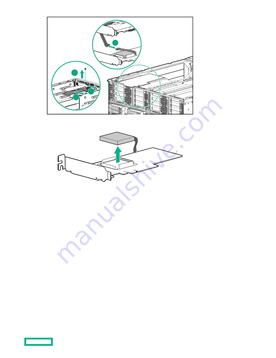
4. Remove the battery from the backup battery card.

5. Insert the replacement backup battery into the tray on the backup battery card.

6. Install the backup battery card.

7. Connect the power cable from the backup battery to the cable attached to the storage controller card.

8. Install the rear air baffles.

9. Install the rear chassis cover.

After storage controller backup battery replacement

Procedure

1. Slide the chassis into the rack and reconnect the cables.

a. Connect the UPI cables to the front of the chassis.

b. Connect the I/O cables and power cords to the rear of the chassis.

2. Connect power to the system but do not power on the system.

3. To verify cabling, run 

test upi

.

Storage controller backup battery replacement

54

Содержание Flex 280

Страница 1: ...enance and Service for HPE Superdome Flex 280 Server Part Number 10 192005 Q321 Published June 2021 Edition 4 Abstract Customer maintenance part replacement and related procedures for HPE Superdome Fl...

Страница 2: ...onsible for information outside the Hewlett Packard Enterprise website Acknowledgments Intel Itanium Optane Pentium Xeon Intel Inside and the Intel Inside logo are trademarks of Intel Corporation or i...

Страница 3: ...ystem overview 17 UPI processor interconnections 19 HPE Superdome Flex 280 Server environmental specifications 21 HPE Superdome Flex 280 Server physical specifications 22 HPE Superdome Flex 280 Server...

Страница 4: ...system 42 GPU card replacement 43 Preparing for GPU card replacement 43 Replacing a GPU card 43 After GPU card replacement 44 Memory DIMM replacement 46 Preparing for Memory DIMM replacement 46 Replac...

Страница 5: ...56 Websites 57 Support and other resources 58 Accessing Hewlett Packard Enterprise Support 58 Accessing updates 58 Remote support 59 Warranty information 59 Regulatory information 59 Documentation fe...

Страница 6: ...7 4 1 Item Description 1 PCIe and GPU cards 2 DIMM 3 Processor 4 Fan 5 Power supply 6 BMC Base I O cards NOTE Available with base chassis and not with expansion chassis 7 Disk drive Mechanical compon...

Страница 7: ...2 5 Item Description 1 Panel assembly UPI filler 2 Bezel assembly 3 Front air baffle assembly 4 Rear air baffle assembly 5 Air seal NOTE Air seal is available with 2 socket configuration System compon...

Страница 8: ...on the equipment to indicate the presence of potentially hazardous conditions WARNING This symbol indicates the presence of hazardous energy circuits or electric shock hazards Refer all servicing to...

Страница 9: ...t down the server and remove the power cord Installation and maintenance of this product must be performed by individuals who are knowledgeable about the procedures precautions and hazards associated...

Страница 10: ...of Thermal Insulation Material TIM thermal grease if replacing a processor 0 5 g thermal grease syringe PN 741909 001 1 0 g thermal grease syringe PN 741910 001 Alcohol pads ESD strap One or more of...

Страница 11: ...able must be connected from the base chassis eRMC port to the manageability network An IP address must be configured for the eRMC Procedure 1 Use a web browser to access the RMC web GUI at https RMC I...

Страница 12: ...load the device driver and setup instructions from https www ftdichip com Drivers D2XX htm Windows 10 systems do not have the FT230X driver installed by default NOTE CNSL connection with Windows 7 and...

Страница 13: ...ort RMC CLI one is the SMC port unused no customer or service feature and the other port also is unused 4 Use PuTTY or another terminal program to connect to the COM port Establish a serial connection...

Страница 14: ...P example rmc eRMC r001u01c cli help Commands type help command for more information acquit clear deconfig generate ping remove show add collect disable help ping6 restore test apropos commands downlo...

Страница 15: ...Y TO REMOVE CNSL Figure 3 CNSL port on chassis rear 2 Use cu or minicom to connect to the dev ttyACM1 device linux minicom D dev ttyACM1 Connect at 115200 baud using 8 data bits 1 stop bit no parity X...

Страница 16: ...b The base chassis is located in the lowest U position in the rack 8 9 10 11 12 13 14 15 16 8 9 10 11 12 13 14 15 16 PEER eRMC CLOCK 0 1 eRMC VGA RST CNSL SERIAL USB USB LAN1 LAN0 PUSH LATCH DOWN AND...

Страница 17: ...es of HPE Superdome Flex 280 Server include Supports 2 4 6 and 8 processor sockets with Intel Xeon 53xx 63xx and 83xx Cooper Lake processors in a two chassis system for example when populated with 28...

Страница 18: ...Up to 16 PCIe Gen 3 slots Eight fans Two or four power supplies BaseIO management management USB port and Ethernet ports base chassis only System overview 18...

Страница 19: ...Two chassis configurations are connected with external UPI cables x8 x16 x8 x16 Memory Processor Legend I O UPI x16 x8 x16 x8 x16 x8 x16 x8 x8 x16 x8 x16 SMC TPM BMC PCH 0 1 2 3 Base IO Figure 6 Supe...

Страница 20: ...sor Base IO Expansion Legend I O UPI x8 x16 x8 x16 x16 x8 x16 x8 x8 x16 x8 x16 x16 x8 x16 x8 x8 x16 x8 x16 x16 x8 x16 x8 x8 x16 x8 x16 0 1 2 3 3 1 2 0 Figure 7 Superdome Flex 280 Server two chassis sy...

Страница 21: ...dissipation fully populated system 17 40 kBTU hr Air quality Gaseous contaminants must be at the G1 level or less as defined by ISA Standard ISA 71 04 1985 Humidity Recommended Operating Range noncond...

Страница 22: ...Table 2 HPE Superdome Flex 280 Server chassis physical specifications Depth from front fan handle to rear BaseIO or BMC tray handle 879 5 mm 34 63 inch Width 445 mm 17 5 inch Height 5U 218 2 mm 8 59...

Страница 23: ...lex 280 Server configuration options see www hpe com support superdomeflex280 quickspecs Table 3 HPE Superdome Flex 280 Server chassis electrical specifications Single phase 200 240 Volts 4 IE320 C13...

Страница 24: ...s slides forward and backward in the rack to provide access to internal components Figure 8 Chassis slid forward in rack Figure 9 Chassis slid backward in rack To provide proper clearance for the chas...

Страница 25: ...nd any I O cables from the rear of the chassis Figure 11 Disconnecting the power and I O cables Using the service shelf If the chassis is in rack position U01 or U06 use the service shelf when you rep...

Страница 26: ...Using the service shelf with the legs folded 1 2 3 4 5 6 7 WARNING Always use two people when moving a chassis onto the service shelf flipping the chassis over or putting the chassis back in the rack...

Страница 27: ...g the chassis back in the rack A fully loaded chassis weighs approximately 125 lbs 57 kg Do not attempt to remove a chassis from a rack by yourself Procedure 1 Place the shelf with the legs unfolded i...

Страница 28: ...de and lift the cover off the chassis Removing the PCIe riser cover The PCIe riser cover is under the rear cover Procedure Remove the PCIe riser cover from the chassis 1 1 2 Remove the two T10 screws...

Страница 29: ...Remove the five T10 screws that secure the cover Slide and lift the cover off the chassis Removing the air baffles The air baffles are located under the top covers There are two or four air baffles de...

Страница 30: ...of the chassis that does not have processors Procedure To remove the air seal remove the two screws that secure it to cable management bracket and lift the air seal out of the chassis 2 1 1 Removing...

Страница 31: ...able wraps disconnect the PCIe riser cables from each other and then move the cables out of the cable management bracket 2 1 1 1 Remove the cable wraps that secure the PCIe riser power cables to the c...

Страница 32: ...chassis configurations include a GPU support bracket This bracket must be removed to replace the motherboard Procedure 1 Remove the T10 screws and then remove the U bracket 1 1 2 Remove the two T10 s...

Страница 33: ...he chassis over or access it from underneath WARNING Always use two people when moving a chassis onto the service shelf flipping the chassis over or putting the chassis back in the rack A fully loaded...

Страница 34: ...Remove the two T10 screws through the front bulkhead Slide and lift the cover off the chassis Accessing components 34...

Страница 35: ...up Leave the system stowed in the rack In other configurations you might need to shut down the operating system before replacing a drive Replacing an HDD SSD Procedure 1 Locate the drive to replace 2...

Страница 36: ...ve handle until the drive locks in place After disk drive replacement 1 Check the status of the disks at the UEFI Shell device manager Confirm that the disks are shown and attached to a RAID controlle...

Страница 37: ...3 Shut down the operating system 4 Power down the system 5 Disconnect the chassis from site power 6 Provide clearance for the chassis to slide in the rack a Remove the bezel b Remove the power cables...

Страница 38: ...ide the DVD drive out the front of the chassis 4 Slide the replacement DVD drive into the DVD slot 5 Secure the replacement DVD drive with one T10 Torx screw tightened to 5 in lb 6 Connect the data an...

Страница 39: ...otopt uefishell 5 To confirm that there are no CRC errors or dropped lanes run test upi again eRMC cli test upi 6 Check the status of the system hardware eRMC cli show health eRMC cli show complex eRM...

Страница 40: ...s the faulty fan from the front of the chassis Two chassis system Procedure 1 To log the hardware status prior to replacing the part run collect rcu eRMC cli collect rcu 2 Remove the bezel Replacing a...

Страница 41: ...ship with fan braces 3 1 2 3 Grasp the handle and slowly pull the fan straight out of the system CAUTION Be careful not to scrape your knuckles on the fan grating It is recommend you wear protective g...

Страница 42: ...hassis system Procedure 1 To verify cabling run test upi eRMC cli test upi Recable and run the utility again if necessary 2 Ensure that there is airflow coming out of the new fan 3 To confirm that the...

Страница 43: ...ove the bezel b Remove the UPI and other cables from the chassis c Remove the power cables from the chassis 5 Slide the chassis out the rear of the rack or remove the chassis from the rack Replacing a...

Страница 44: ...isconnected from the card Ensure that the power cables are properly connected GPU location Power connector on power board PCIe slot 2 J13 PCIe slot 4 J12 PCIe slot 13 J10 PCIe slot 15 J11 7 Install th...

Страница 45: ...confirm that there are no CRC errors or dropped lanes run test upi again eRMC cli test upi 6 Check the status of the system hardware eRMC cli show health 7 Boot the operating system 8 Verify that the...

Страница 46: ...t the chassis from site power 5 Provide clearance for the chassis to slide in the rack a Remove the bezel b Remove the UPI and other cables from the chassis c Remove the power cables from the chassis...

Страница 47: ...J28 J53 J54 J49 J50 J34 J33 J40 J39 J46 J45 Figure 13 Memory DIMM locations 2 If the DIMM is located under the front top cover remove the front top cover and the front air baffles If the DIMM is loca...

Страница 48: ...i show health eRMC cli show complex eRMC cli show npar eRMC cli show cae eRMC cli show indict eRMC cli show deconfig eRMC cli show logs sel 7 Boot the operating system 8 Verify that the memory configu...

Страница 49: ...cables from the chassis c Remove the power cables from the chassis 5 Slide the chassis out the rear of the rack or remove the chassis from the rack Replacing a PCIe card Prerequisites T10 Torx screwd...

Страница 50: ...l the rear top cover 13 Connect any external cables to the card After PCIe card replacement Procedure 1 Slide the chassis into the rack and reconnect the cables a Connect the UPI cables to the front o...

Страница 51: ...dware eRMC cli show health eRMC cli show complex eRMC cli show npar eRMC cli show cae eRMC cli show indict eRMC cli show deconfig eRMC cli show logs sel eRMC cli show deallocate 7 Boot the operating s...

Страница 52: ...re numbered PS0 through PS3 from left to right PUSH LATCH DOWN AND PULL TRAY TO REMOVE PS0 PS1 PS2 PS3 2 Disconnect the power cord 3 Remove the power supply TIP Be sure to note the orientation of the...

Страница 53: ...m 4 Disconnect the chassis from site power 5 Provide clearance for the chassis to slide in the rack a Remove the bezel b Remove the UPI and other cables from the chassis c Remove the power cables from...

Страница 54: ...ntroller card 8 Install the rear air baffles 9 Install the rear chassis cover After storage controller backup battery replacement Procedure 1 Slide the chassis into the rack and reconnect the cables a...

Страница 55: ...cli show cae eRMC cli show indict eRMC cli show deconfig eRMC cli show logs sel 7 Boot the operating system 8 Check the status of the battery To check a battery used with a MegaRAID 9163 4i card use...

Страница 56: ...Spare parts For the list of spare parts available for HPE Superdome Flex 280 Server see www hpe com support superdomeflex280 spareparts Spare parts 56...

Страница 57: ...upport superdomeflex280 spareparts Release sets support matrix www hpe com support superdomeflex280 release sets Safety and regulatory information www hpe com support Safety Compliance EnterpriseProdu...

Страница 58: ...updates Some software products provide a mechanism for accessing software updates through the product interface Review your product documentation to identify the recommended software update method To...

Страница 59: ...www hpe com support ProLiantServers Warranties HPE Enterprise and Cloudline Servers https www hpe com support EnterpriseServers Warranties HPE Storage Products https www hpe com support Storage Warran...

Страница 60: ...ur needs To help us improve the documentation use the Feedback button and icons located at the bottom of an opened document on the Hewlett Packard Enterprise Support Center portal https www hpe com su...

Отзывы: