Solenoid valve control
HE 5712 Compact / Modular
Operating Instructions
(Original German version)
372048 |
Version 1.4
Страница 1: ...Solenoid valve control HE 5712 Compact Modular Operating Instructions Original German version 372048 Version 1 4...
Страница 2: ...randis Editor HESCH Industrie Elektronik GmbH Documentation Department Copyrights Copyright 2020 HESCH Industrie Elektronik GmbH All rights reserved The content including pictures and the design of th...
Страница 3: ...5712 Modular Operating unit panel mounting housing 17 5 ELECTRICAL COMMISSIONING 18 5 1 SAFETY INFORMATION 18 5 2 READ OUT AND SET PASSWORD 19 5 3 SUPPLY VOLTAGE 19 5 3 1 Compact Housing 19 5 3 2 Hous...
Страница 4: ...entering password prior to commissioning 1 3 2020 01 07 Chapter 5 3 and 7 1 12 14 16 added for mass in the note Position of the note in 7 1 adapted Position 11 13 15 added in 7 1 1 4 2020 03 11 Chapte...
Страница 5: ...personal injury or material damage the risk is borne solely by the user Failure to comply with the above criteria for intended use may result in the expiry of the warranty and liability for the device...
Страница 6: ...Warning The severity of the danger is indicated by the respective signal word Explosible region warning sign High Voltage Warning Warning of material damage caused by electrostatic charge Property Da...
Страница 7: ...s no longer possible the device is to be decommissioned and secured against unintentional operation Danger of Electrocution Do not open the device while it is live When opening the devices or removing...
Страница 8: ...hould be taken into consideration If the fault was not found after checking these points we recommend sending the device to the supplier Decommissioning Switch off the power supply on all poles if the...
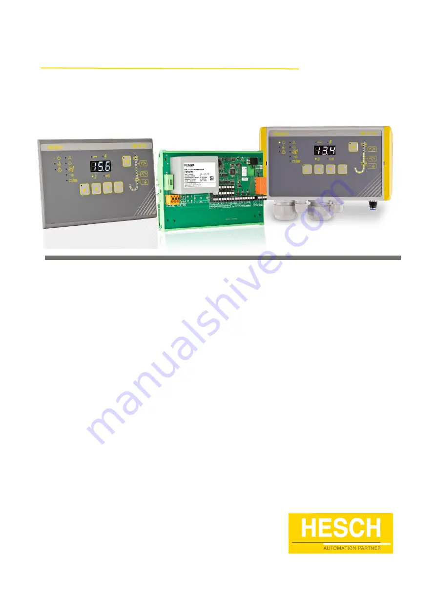
Страница 9: ...ting Instructions 372048 Version 1 4 9 3 Device Description The solenoid valve control HE 5712 is available in different versions 3 1 Overview 3 1 1 HE 5712 Compact HE 5712 Compact HE 5712 Compact Con...
Страница 10: ...10 HE 5712 Operating Instructions 372048 Version 1 4 3 1 2 HE 5712 Modular HE 5712 Modular Operating Unit Rear panel HE 5712 modular Operating Unit...
Страница 11: ...HE 5712 Operating Instructions 372048 Version 1 4 11 HE 5712 Modular control unit in standard rail enclosure 100 240 V AC...
Страница 12: ...eak time The number of valves is shown in the display and can be changed Post cleaning cycles are shown in the display and can be changed Total partial cycle is shown in the display and can be changed...
Страница 13: ...m the displayed value TEST key Test mode On Off Display Normal operation current differential pressure current valve Parameterisation mode parameter values and alarm notes Switch with UP DOWN keys 3 3...
Страница 14: ...s displays 16 LEDs for differential pressure column Keys PARA ESC UP DOWN ENTER TEST Analogue output 4 20 mA max permissible load 400 Digital inputs Start Post cleaning release Relay output 1 change o...
Страница 15: ...onditions Climate Storage 20 70 C Transport 40 85 C Operation Compact housing 20 C 50 C in EX Zone 22 20 40 C Modular 20 C 50 C No EX approval Relative humidity Relative humidity 95 no condensation al...
Страница 16: ...or nominal use specified in the technical data The device version in compact housing may be mounted in areas of explosion class EX ATEX Zone 22 see also the nameplate on the device housing The special...
Страница 17: ...ting unit panel mounting housing Scope of Delivery HE 5712 Operating Instructions Drilling jig only for the operating unit HE 5712 Modular Note Upon receipt check the delivery for completeness and vis...
Страница 18: ...he device must be observed before and during operation Ensure that the FE conductor is connected The patch cable between the control unit and the operating unit may only be plugged unplugged when swit...
Страница 19: ...arts blinking Set the requested value with the UP and DOWN keys 4 When the requested key is displayed press the ENTER key 5 Repeat step 3 and 4 to set the second and third number 6 After the last numb...
Страница 20: ...V DC supply via a patch cable CAT5 or better from the control unit The patch cable must not be longer than 328 feet patch cable not included in the scope of delivery Electrical commissioning of the HE...
Страница 21: ...valve outputs are designed for 24 V DC and 1A The minimum recovery time break must be greater than or equal to ten times the pulse time for software version 1 xx greater than or equal to the pulse ti...
Страница 22: ...the password does not need to be entered again 6 Use the UP and DOWN keys to select the required parameter The current value is displayed 7 Press the ENTER key to change the parameter value The first...
Страница 23: ...5 mbar measuring range 80 0 mbar at 0 90 mbar measuring range 390 0 mbar at 0 450 mbar measuring range Upper threshold mbar If this is exceeded p dependent cleaning starts Start of the p cycle 0 0 500...
Страница 24: ...ls below the threshold a post cleaning cycle is triggered and the cleaning relay is closed for the parameterised post cleaning time OFF 0 0 500 0 mbar 2 0 mbar 2 0 mbar at 0 35 mbar measuring range 5...
Страница 25: ...relay is not switched if the value falls below the final cleaning threshold within the delay 1 600 s 300 s Precoating Offset The precoating offset increases the start threshold for cleaning upper thre...
Страница 26: ...he USB TTL adapter required for this is available from HESCH The parameters can be changed via PC and the EasyTool Controls program The program can be used to save a configuration or to restore a save...
Страница 27: ...device while keeping both keys UP and DOWN pressed for 5 seconds EEP 2 EEP is displayed cod 3 When the 5 seconds are up cod is displayed to enter the password 4 Press the ENTER key to start the passwo...
Страница 28: ...h the set control times The number of cleaning cycles is specified in the parameters see chapter 6 2 Parameter Table Prerequisite The enable input ENABLE is closed To initiate cleaning the enable inpu...
Страница 29: ...t valve If the TEST key is pressed for more than 2 seconds a test cycle is performed on all released valves The active test mode is indicated by the illuminated LED on the TEST key and can be cancelle...
Страница 30: ...bar 4 20 mA 0 20 mbar 4 20 mA In normal operation the cleaning process is started when the upper Cleaning threshold is exceeded and stopped again when the lower Cleaning threshold is reached When the...
Страница 31: ...rential pressure measurement Measuring range of the sensor High alarm Precoating Upper threshold Start Cleansing Lower threshold Stop cleansing Low alarm Start Post cleaning On Cleansing Off On Alarm...
Страница 32: ...in question Check if the valve plug is connected correctly The High Alarm LED flashes The differential pressure exceeds the set threshold Adjust the set pulse and pause times Check filter element Che...
Страница 33: ...generation on the device Disposal Dispatch metals and plastics for recycling Electrical and electronic components must be collected separately and disposed of accordingly Dispose of assembled printed...