background image

Operating Instruction 

95980775

23

EN

Introduction

This 3 

3

4

-digit digital multimeter is an auto-

range automotive multimeter. Besides the 
features of a normal multimeter, it can also 
be used to measure RPM, dwell angle, duty 
cycle, temperature (C;oF), and etc. It is a use-
ful and ideal measurement tool for automo-
tive repair and service.

It can be used to measure:
1.  RPM of engine
2.  Dwell angle
3.  Duty cycle
4.  DC and AC
5.  voltage DC and
6.  AC current
7. Resistance
8. Frequency
9. Diode
10. Temperature (C;oF)
11. Capacitance

Содержание 95980775

Страница 1: ...ELPARTS DE EN FR Multimeter Bedienhinweis ...

Страница 2: ...inleitung 3 Sicherheitshinweise 4 Symbole 5 Anleitung 6 Erklärung der LCD Anzeige 8 Allgemeine Spezifikationen 9 Bedienung 10 Messung des Schließwinkels 14 Drehzahlmessung 15 Wartung 16 Auswechseln der Batterie und Sicherung 16 Spezifikation 17 Kapitel Seite ...

Страница 3: ...zahl Schließwinkel Tastverhält nis Temperatur C F usw messen Es ist ein nützliches Messinstrument das ideal für Reparatur und Instandhaltungsarbeiten an Kraftfahrzeugen geeignet ist Folgende Messungen sind möglich 1 Motordrehzahl 2 Schließwinkel 3 Tastverhältnis Duty Cycle 4 Gleich und Wechselspannung 5 Gleich und Wechselstromstärke 6 Widerstand 7 Frequenz 8 Diode 9 Durchgang 10 Temperatur C F 11 ...

Страница 4: ...r dem Gebrauch durch Messung einer bekann ten Spannung überprüfen 7 Bei Stromstärkemessungen vor dem Anschließen des Messinstruments in der Schaltung Strom abschalten Daran denken das Messinstrument in Reihe zu schalten 8 Bei derWartung des Messinstruments nur vorgeschriebene Ersatzteile verwenden 9 Bei Arbeiten über 30 VAC RMS 42 V Spit ze oder 60 VDC Vorsicht walten lassen Diese Spannungen berge...

Страница 5: ...ss instrument oder dem zu prüfenden Ge rät folgende Richtlinien beachten 1 Vor dem Messen von Widerstand Diode Durchgang Kapazität oder Temperatur Strom abschalten und alle Kondensato ren entladen 2 Die für die Messung richtigen Klemmen richtige Funktion und richtigen Bereich wählen 3 Vor einer Stromstärkemessung die Siche rung des Messinstruments überprüfen und den Strom zur Schaltung abschalten ...

Страница 6: ...lt werden Wenn der Drehschalter in Stellung ist kann mit dieser Taste zwischen folgenden Messungen gewählt werden Wi derstand Diode und Durchgang 5 Funktions Bereichsschalter Mit diesem Schalter können die gewünschte Funktion und der Messbereich gewählt und das Messinstrument ein und ausgeschaltet werden 6 10A Eingang Buchse für die rote Prüfleitung für Strom stärkemessungen 400 mA bis 10 A 7 µAmA...

Страница 7: ...d Ausschalten der Hintergrund beleuchtung Taste drücken und ca 2 Sekun den gedrückt halten 11 Hz Taste Mit dieser Taste kann zwischen Frequenz und Tastverhältnis umgeschaltet werden wenn der Drehschalter auf Hz Duty steht 12 REL Taste Für relative Messungen Eingebauter Summer 1 Beim Drücken einer Taste gibt der einge baute Summer einen Piepton ab wenn der Tastendruck Wirkung erzielt hat 2 Bei der ...

Страница 8: ...utorange Modus ist gewählt 5 Modus Relative Messungen ist aktiviert 6 Data Hold Funktion ist aktiviert 7 Negativ Zeichen 8 Wechselspannung 9 Gleichspannung 10 Die Batterie ist schwach und sollte umgehend ausgewechselt werden Achtung Zur Vermeidung fehlerhafter Messwerte die einen Stromschlag oderVerletzungen zur Folge haben könnten Batterie austauschen sobald die Anzeige Batterie schwach Symbol er...

Страница 9: ...ahrenheit a F 32 1 8 x b C Einheit des Schließwinkels Grad Einheit desTastverhältnisses Duty Cycle Prozent nF µF Einheit der Kapazität nF Nanofarad µF Mikrofarad 1 µF 103 nF Allgemeine Spezifikation Display 3 3 4 stelliges LCD Display mit Anzeige bis 3999 Anzeige der Messbereichsüberschreitung Auf dem LCD Display erscheint OL Anzeige negativer Polarität Es erscheint automatisch Abtastrate ca 2 bis...

Страница 10: ...er RANGE Taste erhöht sich der Messbereich Nach Errei chen des höchsten Messbereichs springt das Messinstrument auf den niedrigsten Messbereich 2 Zum Deaktivieren der manuellen Mess bereichswahl die RANGE Taste drücken und länger als zwei Sekunden halten Das Messinstrument schaltet wieder auf Auto range um Data Hold Funktion Um den aktuellen Messwert auf dem Dis play einzufrieren die HOLD Taste dr...

Страница 11: ... Gleichstrommessungen wird auch die Polarität des Anschlusses der roten Leitung angezeigt Anmerkung Wenn Sie denWert der zu messenden Strom stärke nicht vorher wissen den höchsten Messbereich wählen und dann schrittweise verringern bis eine zufriedenstellende Auf lösung erreicht ist Widerstandsmessung 1 Die schwarze Prüfleitung in den COM Eingang und die rote Prüfleitung in den Eingang stecken Anm...

Страница 12: ...Die rote Prüfleitung an die Anode der zu prüfenden Diode und die schwarze Prüfleitung an die Katode anschließen 4 Im Display erscheint der ungefähre Durchlassspannungsabfall der Diode Wenn der Anschluss umgekehrt wird er scheint im Display OL Frequenzmessung 1 Die schwarze Prüfleitung in den COM Eingang und die rote Prüfleitung in den Eingang stecken 2 Bereichsschalter auf Hz Duty stellen 3 Hz Tas...

Страница 13: ...µAmA C F Eingang stecken 2 Bereichsschalter auf C oder F stel len 3 Das Ende des Thermoelements in den zu messenden Bereich bringen 4 Warten bis der Messwert stabil ist Auf dem Display Messwert ablesen Kapazitätsmessung 1 Die schwarze Prüfleitung in den COM Eingang und die rote Prüfleitung in den Eingang stecken Anmerkung Die Polarität der roten Leitung ist positiv 2 Bereichsschalter auf stellen 3...

Страница 14: ...der gefolgt von CYL 4 Die schwarze Prüfleitung an die Masse klemme oder den Minuspol der Batterie und die rote Prüfleitung an die Nieder spannungsklemme des Verteilers oder den Minuspol der Zündspule anschlie ßen 5 Motor anlassen und auf dem Display Messwert ablesen Anmerkungen 1 Die Eingangsspannung muss zwischen 3 und 50 Vp liegen Ist die Spannung zu niedrig kann keine Winkelmessung durchgeführt...

Страница 15: ...y Messwert ablesen Anmerkungen 1 Die Eingangsspannung muss zwischen 3 und 50 Vp liegen Ist die Spannung zu niedrig kann keine Drehzahlmessung durchgeführt werden 2 Die Stabilität der Messwertanzeige nimmt ab wenn die Drehzahl des Motors zu niedrig ist 3 Die Polarität der Eingangsspannung muss richtig sein Anderenfalls ist die Messung nicht möglich Automatische Abschaltung Wenn das Messinstrument c...

Страница 16: ...ln der Batterie und Sicherung Achtung Zur Vermeidung fehlerhafter Messwerte die einen Stromschlag oder Verletzungen zur Folge haben könnten Batterie austauschen sobald die Anzeige Batterie schwach erscheint Zur Vermeidung von Schäden oder Verletzungen nur Sicherungen dersel ben Bemessung verwenden Vor dem Öffnen der Rückwand oder der Batterieabdeckung die Prüfleitungen abziehen Zum Auswechseln der...

Страница 17: ...ichspannung DC Messbereich Auflösung Messgenauigkeit 400 mV 0 1 mV 1 0 5 4 V 1 mV 0 8 3 40 V 10 mV 0 8 3 250 V 100 mV 0 8 3 Eingangsimpedanz Messbereich 400 mV 1000 MΩ andere Messbereiche 10 MΩ Maximal zulässige Eingangsspannung 250 V DC AC Wechselspannung AC Messbereich Auflösung Messgenauigkeit 4 V 0 001 V 1 0 5 40 V 0 01 V 1 0 5 250 V 0 1 V 1 0 5 Eingangsimpedanz 10 MΩ Maximal zulässige Eingang...

Страница 18: ...ingänge 5 A Messdauer 15 s Abstand 15 Minuten Maximaler Spannungsabfall 400 mV Wechselstromstärke AC Messbereich Auflösung Messgenauigkeit 400 µA 0 1 µA 1 5 5 4000 µA 1 µA 1 5 5 40 mA 10 µA 1 5 5 400 mA 100 µA 1 5 5 4 A 1 mA 2 0 5 10 A 10 mA 3 0 10 Überlastungsschutz µAmA C F Eingänge Flink Sicherung 500 mA 250 V 10A Eingänge keine Absicherung Eingänge 5 A Messdauer 15 s Abstand 15 Minuten Maximal...

Страница 19: ... kHz 0 8 3 500 Hz 0 1 Hz 0 8 3 5 kHz 1 Hz 0 8 3 50 kHz 10 Hz 1 0 3 200 kHz 100 Hz 1 0 3 200 kHz Nicht festgelegt Messbereich 1 bis 20 V RMS Überlastungsschutz 250 V DC AC Diode und Durchgang Messbereich Einführung Prüfbedingungen Der ungefähre Durchlassspannungs abfall der Diode wird angezeigt Leerlaufspannung ca 1 5 V Der eingebaute Summer ertönt wenn der Widerstand weniger als ca 50 Ω beträgt De...

Страница 20: ...10 Vp p Überlastungsschutz 250 V DC AC Temperatur Messbereich Auflösung Messgenauigkeit 20 bis 1000 C 1 C 20 bis 0 C 6 0 5 1 C 0 bis 400 C 1 5 5 1 C 400 C 1 8 5 4 bis 1832 F 1 F 4 bis 32 F 6 0 9 1 F 32 bis 752 F 1 5 9 1 F 752 C 1 8 9 Überlastungsschutz Flink Sicherung 500 mA 250 V Anmerkungen 1 Die Messgenauigkeit schließt nicht den Fehler desThermoelementfühlers ein 2 Bei den Angaben für die Mess...

Страница 21: ...hzahl Zylinder Messbereich Auflösung Messgenauigkeit 2 250 RPM bis 40 kRPM 1 RPM 2 5 5 3 250 RPM bis 40 kRPM 1 RPM 2 5 5 4 250 RPM bis 40 kRPM 1 RPM 2 5 5 5 250 RPM bis 40 kRPM 1 RPM 2 5 5 6 250 RPM bis 40 kRPM 1 RPM 2 5 5 8 250 RPM bis 40 kRPM 1 RPM 2 5 5 Eingangsspannung 3 bis 50 Vp Überlastungsschutz 250 V DC AC Anmerkung Bei Messungen an Viertaktmotoren ent spricht derWert auf dem Display der ...

Страница 22: ...nts Introduction 23 Safety information 24 Symbols 25 Instruction 26 LCD explanation 28 General specification 29 Operation instruction 30 Measuring Dwell Angle 34 Measuring EngineTach 35 Maintenance 36 Replacing the Battery and Fuse 36 Specification 37 Chapter Page ...

Страница 23: ...rmal multimeter it can also be used to measure RPM dwell angle duty cycle temperature C oF and etc It is a use ful and ideal measurement tool for automo tive repair and service It can be used to measure 1 RPM of engine 2 Dwell angle 3 Duty cycle 4 DC and AC 5 voltage DC and 6 AC current 7 Resistance 8 Frequency 9 Diode 10 Temperature C oF 11 Capacitance ...

Страница 24: ...g the meter in the circuit Remember to place the meter in series with the circuit 8 When servicing the meter use only spec ified replacement parts 9 Use caution when working above 30V ac rms 42V peak or 60V dc Such voltages pose a shock hazard 10 When using the probes keep your fin gers behind the finger guards on the probes 11 When making connections connect the common test lead before you connec...

Страница 25: ...esting resistance diode continuity capacitance or temper ature 2 Use the proper terminals function and range for your measurements 3 Before measuring current check the me ter s fuse and turn off the power to the circuit before connecting the meter to the circuit 4 Before rotating the range switch to change functions disconnect test leads from the circuit under test Remove test leads from the meter...

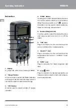
Страница 26: ...tion When the rotary switch is in position this button can be used to select resistance diode or continuity measurement 5 Function Range Switch It can be used to select the desired function and range as well as to turn on or off the meter 6 10A Jack Plug in connector for the red test lead for current 400mA 10A measurements 7 AmA C F Jack Plug in connector for the red test lead for temperature and ...

Страница 27: ... button for about 2 seconds to turn on or off the back light 11 Hz button It can be used to switch the meter between frequency and duty cycle measurements when the rotary switch is in Hz Duty position 12 REL Button It is used for relative measurement Built in Buzzer 1 When you press a button the built in buzzer will give a beep if this press is ef fective 2 In continuity test when the resistance i...

Страница 28: ...tional 4 Autorange mode is selected 5 Relative mode is active 6 Data Hold is enabled 7 Negative sign 8 AC voltage 9 DC voltage 10 The battery is low and should be replaced immediately Warning To avoid false readings which could lead to possible electric shock or personal injury replace the battery as soon as this low battery indicator appears 11 Number of cylinders of the engine to be tested ...

Страница 29: ...00 RPM C F Temperature unit C Celcius degree F Fahrenheit degree a F 32 1 8 x b C Unit of dwell angle Degree Unit of duty cycle Percent nF µF Capacitance unit nF Nanofarad µF Mikrofarad 1 µF 103 nF General specification Display 3 3 4 digit LCD with a max reading of 3999 Overrange Indication OL shown on the LCD Negative Polarity Indication displayed automatically Sampling Rate About 2 3 times sec O...

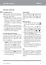
Страница 30: ...raps to the lowest range 2 To exit the manual range mode press and hold down the RANGE button for more than 2 seconds the meter returns to the autorange mode Data Hold Mode Press the HOLD button to hold the present reading on the display appears on the display as an indicator To exit the Data Hold mode press the button again disap pears Measuring Voltage 1 Connect the black test lead to the COM ja...

Страница 31: ...nect the black test lead to the COM jack and the red test lead to the jack Note The polarity of the red lead is positive 2 Set the range switch to Ω range Ω ap pears on the display 3 Connect the test leads across the load to be measured 4 Read the reading on the display Note 1 For resistance above 1MΩ the meter may take a few seconds to stabilize read ing This is normal for high resistance measure...

Страница 32: ... Hz Duty position 3 Press the Hz button until the display shows Hz 4 Connect the test leads across the source or load to be measured 5 Read the reading Note The voltage of the input signal should be be tween 1V rms and 20V rms If the voltage ex ceeds 20V rms the accuracy of reading may be out of the specified accuracy range Measuring Duty Cycle 1 Connect the black test lead to the COM jack and the...

Страница 33: ...eading is stable read the reading on the display Measuring Capacitance 1 Connect the black test lead to the COM jack the red test lead to the jack Note The polarity of the red lead is posi tive 2 Set the range switch to position 3 Connect the test leads across the capaci tor to be measured 4 Wait until the reading is stable then read the reading For high capacitance meas urements it may take about...

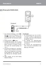
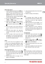
Страница 34: ...y CYL 4 Connect the black test lead to ground or the negative terminal of the battery and the red test lead to the low voltage ter minal of the distributor or the negative terminal of the ignition coil 5 Start the engine and read the reading on the display Note 1 The input voltage must be between 3Vp and 50Vp If the voltage is too low it will be impossible to perform dwell measure ment 2 Reading s...

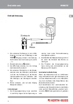
Страница 35: ...nition coil 5 Start the engine and read the reading on the display Note 1 The input voltage must be between 3Vp and 50Vp If the voltage is too low the speed measurement cannot be carried out 2 Reading s stability will decrease if the ro tation speed of the engine is too low 3 The polarity of the input voltage must be correct otherwise it will be impossible to perform the measurement Auto Power Off...

Страница 36: ...very terminal Replacing the Battery and Fuse Warning To avoid false readings which could lead to possible electric shock or personal injury replace the battery as soon as the battery indicator appears To prevent damage or injury install only re placement fuse of the same ratings Discon nect the test leads before opening the back cover or the battery cover To replace the battery remove the screws o...

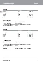
Страница 37: ... Dig its DC Voltage Range Resolution Accuracy 400 mV 0 1 mV 1 0 5 4 V 1 mV 0 8 3 40 V 10 mV 0 8 3 250 V 100 mV 0 8 3 Input Impedance range 400 mV 1000 MΩ the other ranges 10 MΩ Max Permitted Input Voltage 250 V DC AC AC Voltage Range Resolution Accuracy 4 V 0 001 V 1 0 5 40 V 0 01 V 1 0 5 250 V 0 1 V 1 0 5 Input Impedance 10 MΩ Max Permitted Input Voltage 250 V DC AC Frequency Range 40 400 Hz Resp...

Страница 38: ...n For inputs 5A measurement duration 15 secs interval 15 minutes Maximum Voltage Drop 400 mV AC Current Range Resolution Accuracy 400 µA 0 1 µA 1 5 5 4000 µA 1 µA 1 5 5 40 mA 10 µA 1 5 5 400 mA 100 µA 1 5 5 4 A 1 mA 2 0 5 10 A 10 mA 3 0 10 Overload Protection For µAmA C F jack inputs Fuse 500 mA 250 V fast action For 10A jack inputs no fuse protection For inputs 5A measurement duration 15 secs int...

Страница 39: ...3 4 MΩ 1 kΩ 1 0 3 40 MΩ 0 01 MΩ 2 0 5 Open Circuit Voltage about 0 45Vdc Overload Protection 250V DC AC Frequency Range Resolution Accuracy 5 Hz 0 001 kHz 1 0 3 50 Hz 0 01 kHz 0 8 3 500 Hz 0 1 Hz 0 8 3 5 kHz 1 Hz 0 8 3 50 kHz 10 Hz 1 0 3 200 kHz 100 Hz 1 0 3 200 kHz Not Specified Measurement Range 1Vrms 20Vrms Overload Protection 250V DC AC ...

Страница 40: ...on Test Condition The approx forward voltage drop Open Circuit Voltage of diode will be displayed about 1 5 V The built in buzzer will sound Open Circuit Voltage if the resistance is less than about 0 45 V about 50Ω The buzzer will not sound if the resistance is more than 120Ω Overload Protection 250V DC AC Duty Cycle Range Resolution Accuracy 5 95 0 1 1 Hz bis 10 kHz 2 5 5 95 0 1 10 kHz not speci...

Страница 41: ...s not include error of the thermocouple probe 2 Accuracy specification assumes ambient temperature is stable to 1 C For ambi ent temperature changes of 5 C rated accuracy applies 1 hour later after the temperature change Dwell Angle Cylinders Range Resolution Accuracy 2 0 180 0 1 2 5 5 3 0 120 0 1 2 5 5 4 0 90 0 1 2 5 5 5 0 72 0 1 2 5 5 6 0 60 0 1 2 5 5 8 0 45 0 1 2 5 5 Input Voltage 3 50 Vp Requi...

Страница 42: ... 40 kRPM 1 RPM 2 5 5 5 250 RPM 40 kRPM 1 RPM 2 5 5 6 250 RPM 40 kRPM 1 RPM 2 5 5 8 250 RPM 40 kRPM 1 RPM 2 5 5 Input Voltage 3 50 Vp Overload Protection 250 V DC AC Note For measurements of 4 stroke engine the reading on the display equals the actual rotation speed of the engine For measurements of 2 stroke engine the actual rotation speed is one half of the read ing on the display ...

Страница 43: ...nsignes de sécurité 45 Symboles 46 Description 47 Explication de l affichage LCD 49 Caractéristiques générales 50 Utilisation 51 Mesure de l angle de came 55 Mesure du régime 56 Entretien 57 Remplacement de pile et de fusible 57 Caractéristiques 58 Chapitre Page ...

Страница 44: ... le régime l angle de came les taux d impulsions la température C F etc Il s agit d un instrument de mesure utile qui est particulièrement approprié pour les opérations de réparation et d entretien sur véhicules automobiles Voici les mesures qu il permet d effectuer 1 Régime moteur 2 Angle de came 3 Taux d impulsions Duty Cycle 4 Tension continue et alternative 5 Intensité du courant continu et al...

Страница 45: ...et la masse 6 Avant toute mise en service de l instru ment de mesure vérifier son fonctionne ment par la mesure d une tension connue 7 Lors de mesures d intensité de courant couper le courant avant de raccorder l instrument de mesure au circuit Veiller à utiliser l instrument de mesure en série 8 Lors de l entretien de l instrument de me sure utiliser exclusivement les pièces de rechange stipulées...

Страница 46: ... catégories de mesure III et IV Attention Afin d éviter tout risque de détérioration de l instrument de mesure ou de l appareil sou mis au contrôle il convient d observer les consignes suivantes 1 Avant toute mesure d une résistance d une diode de continuité de la capacité ou d une température couper l alimen tation électrique et décharger tous les condensateurs 2 Veiller à sélectionner les bornes...

Страница 47: ...et continuité 5 Sélecteur de fonction plage Ce commutateur permet de sélectionner la fonction et la plage de mesure souhaitées et d allumer et d éteindre l instrument de mesure 6 Entrée 10 A Prise femelle pour le câble de contrôle rouge pour les mesures de l intensité de courant 400 mA à 10 A 7 Entrée µAmA C F Prise femelle pour le câble de contrôle rouge pour les mesures de la température et de l...

Страница 48: ...uche Hz Cette touche permet de passer de la fré quence au taux d impulsions lorsque le commutateur rotatif est positionné sur Hz Duty 12 Touche REL Pour les mesures relatives Système sonore intégré 1 À la pression d une touche le système sonore intégré émet un bip lorsque la fonction activée par la touche sélection née est exécutée 2 Lors du contrôle de continuité le sys tème sonore émet un bip lo...

Страница 49: ...ique sélectionné 5 Modus Relative Messungen ist aktiviert 6 Mode Mesures relatives activé 7 Signe négatif 8 Tension alternative 9 Tension continue 10 La pile est faible et doit être remplacée immédiatement Attention Pour éviter toute valeur de mesure erronée susceptible de provoquer un choc électrique et d infliger des blessures remplacer la pile dès l affichage du symbole Pile faible 11 Nombre de...

Страница 50: ...egré Fahrenheit a F 32 1 8 x b C Unité de l angle de came degré Unité du taux d impulsions Duty Cycle pourcentage nF µF Unité de capacité nF nanofarad µF microfarad 1 µF 103 nF Caractéristiques générales Écran LCD 3 3 4 avec affichage numérique max 3999 Affichage du dépassement de la plage de mesure Indiqué sur l écran LCD par OL Affichage polarité négative s affiche automatiquement Fréquence d éc...

Страница 51: ...de la plage de mesure AUTO disparaît alors de l écran À chaque pression de la touche RANGE la plage de mesure augmente Une fois que le seuil maximal de la plage de me sure est atteint l instrument de mesure passe automatiquement au seuil mini mal 2 Pour désactiver le mode manuel de sé lection de la plage de mesure appuyer sur la touche RANGE en la maintenant enfoncée pendant plus de deux se condes...

Страница 52: ...esurée et raccorder les câbles de contrôle au circuit en série 6 Mettre le circuit sous tension et lire la va leur de mesure à l écran Lors des mesures de courant continu la polarité du raccord du câble rouge s affiche également Remarque Si la valeur de l intensité du courant à mesu rer n est pas connue au préalable opter pour la plage de mesure la plus élevée et réduire ensuite progressivement ju...

Страница 53: ...der le câble de contrôle rouge à l anode de la diode devant être vérifiée et le câble de contrôle noir à la cathode 4 La chute approximative de tension directe de la diode apparaît à l écran Si le raccordement est inversé OL s affiche à l écran Mesure de la fréquence 1 Brancher le câble de contrôle noir dans l entrée COM et le câble rouge dans l en trée 2 Positionner le sélecteur de plage sur Hz D...

Страница 54: ...ner le sélecteur de plage sur C ou F 3 Placer l extrémité du thermoélément dans la zone de mesure 4 Attendre que la valeur de mesure se stabilise Lire la valeur de mesure sur l écran Mesure de capacité 1 Brancher le câble de contrôle noir dans l entrée COM et le câble rouge dans l entrée Remarque la polarité du câble de contrôle rouge est positive 2 Positionner le sélecteur de plage sur 3 Placer l...

Страница 55: ...e contrôle noir à la borne de masse ou à la cosse négative de la batterie et le câble de contrôle rouge à la borne basse tension de l allumeur ou à la borne négative de la bobine d allu mage 5 Démarrer le moteur et relever la valeur de mesure affichée à l écran Remarques 1 La tension à l entrée doit se situer entre 3 et 50 Vp Si la tension est trop basse il est impossible de connaître le régime mo...

Страница 56: ...relever la valeur de mesure affichée à l écran Remarques 1 La tension à l entrée doit se situer entre 3 et 50Vp Si la tension est trop basse i il sera impossible de réaliser une mesure de l angle 2 La stabilité de l affichage de la valeur de mesure diminue lorsque le régime mo teur est trop faible 3 La polarité de la tension à l entrée doit être exacte faute de quoi la mesure ne sera pas réalisabl...

Страница 57: ...Remplacement de pile et de fusible Attention Pour éviter toute valeur de mesure erronée susceptible de provoquer un choc électrique et d infliger des blessures remplacer la pile dès l affichage du symbole Pile faible Pour éviter tout risque de détérioration ou de blessures utiliser uniquement des fusibles de même type et de même calibre Avant l ouverture de la face arrière ou du cache de la pile v...

Страница 58: ...lus basse Tension continue CC Plage de mesure Résolution Précision de mesure 400 mV 0 1 mV 1 0 5 4 V 1 mV 0 8 3 40 V 10 mV 0 8 3 250 V 100 mV 0 8 3 Impédance d entrée Plage de mesure 400 mV 1 000 MΩ Autres plages de mesures 10 MΩ Tension maximale admise à l entrée 250 V CC CA Tension alternative CA Plage de mesure Résolution Précision de mesure 4 V 0 001 V 1 0 5 40 V 0 01 V 1 0 5 250 V 0 1 V 1 0 5...

Страница 59: ...s de mesure 15 s intervalle 15 minutes Chute de tension maximale 400 mV Intensité du courant alternatif CA Plage de mesure Résolution Précision de mesure 400 µA 0 1 µA 1 5 5 4 000 µA 1 µA 1 5 5 40 mA 10 µA 1 5 5 400 mA 100 µA 1 5 5 4 A 1 mA 2 0 5 10 A 10 mA 3 0 10 Protection contre la surtension Entrées µAmA C F Fusible Flink 500 mA 250 V Entrées 10 A sans fusible Entrées 5 A temps de mesure 15 s ...

Страница 60: ...3 4 MΩ 1 kΩ 1 0 3 40 MΩ 0 01 MΩ 2 0 5 Tension à vide env 0 45 VDC Protection contre la surtension 250 V CC CA Fréquence Plage de mesure Résolution Précision de mesure 5 Hz 0 001 kHz 1 0 3 50 Hz 0 01 kHz 0 8 3 500 Hz 0 1 Hz 0 8 3 5 kHz 1 Hz 0 8 3 50 kHz 10 Hz 1 0 3 200 kHz 100 Hz 1 0 3 200 kHz Non définie Plage de mesure 1 à 20 V RMS Protection contre la surtension 250 V CC CA ...

Страница 61: ...hute approximative de tension directe de la diode est affichée Tension à vide env 1 5 V Le système sonore intégré émet un bip si la résistance est inférieure à 50 Ω environ Le système sonore n émet pas de bip si la résistance est supérieure à 120 Ω Tension à vide env 0 45 V Protection contre la surtension 250 V CC CA Taux d impulsions Duty Cycle Plage de mesure Résolution Précision de mesure 5 à 9...

Страница 62: ...l erreur de la sonde thermo couple 2 Dans les données pour la précision de mesure la température ambiante est donnée pour stable à 1 C En cas de changement de la température ambiante de 5 C la précision nominale s applique une heure après le changement de température Angle de came Cylindre Plage de mesure Résolution Précision de mesure 2 0 à 180 0 1 2 5 5 3 0 à 120 0 1 2 5 5 4 0 à 90 0 1 2 5 5 5 0...

Страница 63: ...5 5 5 250 RPM à 40 kRPM 1 RPM 2 5 5 6 250 RPM à 40 kRPM 1 RPM 2 5 5 8 250 RPM à 40 kRPM 1 RPM 2 5 5 Tension à l entrée 3 à 50 Vp Protection contre la surtension 250 V CC CA Remarque Dans le cas de mesures sur des moteurs à quatre temps la valeur affichée corres pond au régime moteur réel Dans le cas de mesures sur des moteurs à deux temps le régime réel est la moitié de la valeur affichée à l écra...

Страница 64: ... DE 63150 Heusenstamm Herth Buss France SAS ZA Portes du Vercors 270 Rue Col de La Chau FR 26300 Châteauneuf sur Isère Herth Buss Belgium Sprl Rue de Fisine 9 ı BE 5590 Achêne Herth Buss UK Ltd Ground Floor Unit 16 Londonderry Farm Keynsham Road Willsbridge Bristol ı UK BS30 6 EL ...

Отзывы: