I n s t a l l a t i o n , O p e r a t i o n , & M a i n t e n a n c e M a n u a l
9
www.herrmidifier-hvac.com
Wiring
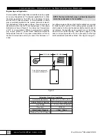
All field wiring should be routed up through the holes in the
bottom panel or in the back of the unit.
Figure 7 (Bottom View)
Supply Power
1. Ensure that minimum circuit amperage capacity is 15 amps.
2. Terminals are provided in the electrical compartment for
field connection of the main power supply legs (single
phase) and a ground wire.
3. Install external overcurrent protection and provide wiring in
accordance with the NEC, state and local codes.
4.
Power supply must be “clean”: free of spikes, surges and
sags: -15% to +10% of nominal.
Electrical Characteristics:
Model
6500-1
6500-2
lbs/hr
4
8
kg/hr
1.8
3.6
Voltage
115
230
Amps
11.5
11.5
kW
1.33
2.66
BOTTOM VIEW
1.56
.75
Ø.88 THRU HOLE
2.37
Herrtronic
®
Model 6500
Control Circuit Connections
WARNING!
Do NOT install any controls inside the HERRMIDIFIER
6500 cabinet. Installations of any extraneous devices
inside the electrical compartment may cause erratic
behavior of the circuitry and will VOID the warranty.
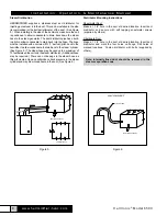
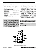
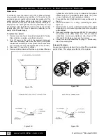
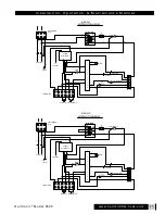
The control wiring for the humidifier is to be connected to
the controls wiring terminal strip located in the electrical
compartment. Terminals #1 and #2 are to power an electronic
humidistat (24 VAC). Terminals #3 and #4 are to connect the
control and high limit humidistat (included). Terminals #5 and
#6 are to connect air proving switch (included). All control wiring
should be 22 AWG or larger. (See Figure 8.) Consult with the
factory if you have any special wiring requirements.
Figure 8
Figure 9
G
R
THERMOSTAT
TERMINALS
267575-001
AUXILARY RELAY
INSIDE CABINET
4
3
2
1
AIR PROVING SWITCH
(INCLUDED)
CONTROL WIRING
5 6
HIGH LIMIT
CONTROL
HUMIDISTAT
(INCLUDED)
HUMIDISTAT
(INCLUDED)
TERMINALS FOR POWERING
ELECTRONIC HUMIDISTAT
24V HOT
24V COM.


