


HENR
Y
T
OOLS,
INC.
Ph: (216) 291-1011 or (800) 826-5257
General Operators Instructions and Service Manual
www.HenryTools.com | Page 251
Revised 04/11/11
For additional product information visit our website.
LUBRICATION
Lubricate the motor with an air line lubricator,
using a light air motor oil. Adjust the lubricator
to dispense one drop per cycle or three drops per
minute.
CAUTION Do not use substitutes for oil and grease.
This could result in damage to the tool.
MAINTENANCE
1. Proper and continuous lubrication.
2. Blow out air hose to assure a clean air supply.
3. Be sure the air filter and line lubricator are clean.
4. Fill the line lubricator before operation.
5. Place a few drops of oil into the air inlet of the
tool be-fore attaching the air line.
6. Use moisture separators to remove water from
the air line.
7. An air line filter-regulator-lubricator should be
located as closely as possible to the tool.
8. Keep screen handle bushing in tool.
WARNING: Disconnect the air supply hose before
servicing the tool.
Disassembly
1. Secure tool in vise vertically with output of
tool oriented toward upward direction. Clamp onto
the flats toward the rear of the motor housing.
2. Unscrew motor retainer (403-38) from motor
housing(402-132). Lift off exhaust deflector(410-G-
17-S) and o-ring (400-51)if worn from motor hous-
ing. Remove motor assembly from housing.
3. Secure motor assembly into vise vertically with
output in the downward direction. Clamp onto
flats on the collet body (1100-672).
4. Remove snap ring (404-39) from rear endplate
(404-19) with use of snap ring pliers.
5. Lift out bearing cover (404-38) and o-ring
(594016).
6. Remove snap ring (592016) from groove of
rotor (4031-5A).
7. Using a soft-jawed vise. Secure motor assem-
bly into vise vertically with output toward down-
ward direction. Clamp lightly the outside diameter
of the cylinder (400-2G) and endplate (404-19).
8. Use a 3/16” punch to tap spindle out of rear
bearing (404-9).
D
o
NoT
drop the motor assembly
when it is free. Remove from vise.
9. Use a small punch to press the rear bearing
from the rear endplate.
10. Remove the 5 blades (400-6).
11. With soft jaws still in vise, clamp firmly onto
rotor (4031-5A) with output toward upward posi-
tion. Remove collet body (1100-672) (right hand
thread). Remove from vise.
12. Support the rotor assembly on a suitable drill
block. Press the spindle through the front bearing
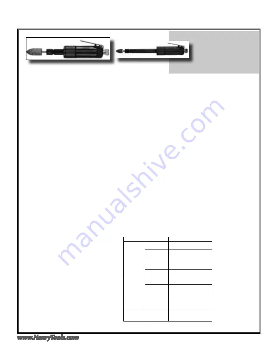
MODEL
4123GL
6”
assy. using an arbor press. Use a small punch to remove front bearing (590031)
from front endplate(403-7).
13. (o
pTioNal
S
Tep
)
: To check throttle valve unscrew throttle valve cap (869311).
14. 14.
(o
pTioNal
S
Tep
)
: Lift out valve spring (400-G-34) and throttle valve (400-
G-29). Remove and replace o-ring (844302) if cracked or worn.
Assembly
1. Be sure that all parts are clean.
2. Press bearing (590031) into recessed area of front endplate (403-7).
3. Support the front bearing assembly on a suitable drill block. Press the rotor
(4031-5A) into the rear of front endplate and through front bearing.
4. With soft jaws on vise, clamp firmly onto rotor (4031-5A) with output
toward upward position. Install collet body (1100-672) (right hand thread).
Remove rotor from vise.
5. Secure motor assembly into vise vertically with output in the downward
direction. Clamp onto flats on the collet body (1100-672).
6. Place five blades (400-6) into blade slots.
7. Slip cylinder (400-2G) over rotor and onto endplate. The small pin on face of
cylinder should face toward rear to tool.
8. Place rear endplate (404-19) onto cylinder. Locate the pin of the cylinder
into the small hole of the rear endplate.
9. Press bearing (404-9) into rear endplate with a suitable bearing driver.
10. Install retaining ring (592016) into groove on spindle with snap ring pliers.
11. Place o-ring (594016) and bearing cover (404-38) into rear endplate.
12. Install snap ring (404-39) into groove of reard endplate.
13. Secure motor housing (402-132) in vise vertically with output of tool
toward upward direction. Clamp onto the flats toward the rear of the motor
housing.
14. Place o-ring (400-51), exhaust screen (402-134) and exhaust deflector
(410-G-17-S) onto motor housing.
15. Slide front motor assembly into motor housing. Install motor retainer (403-
38). Tighten assemblies together.
16. Check the operating speed with a reliable tachometer. The speed must be at
or below the stamped speed on the tool.
FAULT
CAUSE
SOLUTION
Insufficient
Power
Air pressure
too low
Minimum air pressure
should
be
90 PSI for maximum performance
Restriction in air
hose
Remove bends or other restric-
tions
Hose I.D. is too
small
Use required hose I.D.
Worn vanes
Exchange vanes (400-6)
Screen Support
clogged
Clean screen support or ex-
change with new one
Machine does
not start
No air, shut-off
valve is closed.
Open shut-off valve
Worn vanes
due to lack of
oil or vanes are
jammed
Exchange vanes . (cylinder might
also be worn out)
Grinder does
not want to
stop
Worn O-Ring
Replace o-ring in handle (844302)
for example.
Spindle
wobbles or
vibrates.
Bearings worn
out .
Danger!!
Disconnect tool from the air
supply.
Immediate
servicing is
required.
6” Model with super extended
length spindle shown above.


