background image


16

Periodic Maintenance 


Daily 


Air Filter


Check air circuit water trap valve and release any water, as 
necessary, through the base outlet. 


Air Lubricator


Check that bowl has oil level above the bottom of the pipe 
within the bowl and refill as necessary.  Bleed off main air 
supply before removing bowl.  Flow rate of oil should be 
approximately one drop per thirty cycles. 


Dispense Head


Remove mix nozzle, purge machine with 3-5 complete 
strokes. Remove lower portions of valve body, clean nose 
assembly and upper spools with solvent and cotton swabs 
(ensure nose assembly is clear of product), wipe rods, spools, 
and seals clean of all material and lubricate with compatible 
lubricant.  If clean re-assemble and lubricate valve through 
grease fitting.  If not completely clean, soak in solvent until 
next production day, clean loosened particles again, re-
assemble and grease. 


Pump Shafts


Clean both pump shafts with solvent and lubricate them with 
Mesamoll. 


Material Reservoirs 


Check material levels in reservoirs and refill as necessary. 


Ratio


Take three consecutive ratio check samples and compare the 
data of each sample for repeatability. 


Lubricating Device 

Fill the lubricating device with grease. 


Weekly 


Dispense Head


Remove mix nozzle, purge machine with 3-5 complete 
strokes. Remove lower portions of valve body, clean nose 
assembly and upper spools with solvent and cotton swabs 
(ensure nose assembly is clear of product), wipe rods, spools, 
and seals clean of all material and lubricate with compatible 
lubricant.  If clean re-assemble and lubricate valve through 
grease fitting.  If not completely clean, soak in solvent until 
next production day, clean loosened particles again, re-
assemble and grease. 


Machine Exterior


Generally clean the machine exterior


Shaft Seal Area


Clean around the shaft area.  If dripping excessively, replace 
shaft seal.


Содержание Loctite

Страница 1: ...Henkel Corporation MMD System 1000 Machine Manual...

Страница 2: ...ispensing even if they may differ from these general instructions Keep the MSDS accessible to the work area as it lists valuable emergency information Consult local state and federal laws before dispo...

Страница 3: ...cessary Danger Labels indicate an imminently hazardous situation which if not avoided could result in death or serious injury Warning Labels indicate potentially hazardous situations which if not avoi...

Страница 4: ...REASSEMBLY AND INSTALLATION 6 ADJUSTING THE SHOT SIZE 7 LOADING THE MACHINE WITH MATERIALS 8 PRIMING THE MATERIAL VALVES 9 PHASING THE PUMPS 10 RATIO CHECK 11 RATIO ADJUSTMENT 12 DAILY OPERATION 13 S...

Страница 5: ...installation adjustment or other expenses which may arise in connection with such goods The liability of Seller arising out of supplying said goods and services or their use whether on warranties or...

Страница 6: ...e ratios metering to a hand held or fixed head mixer or injection of the metered materials through a mixer into open or closed molds The complete system is totally enclosed and mixing of the liquids o...

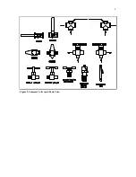
Страница 7: ...ions The 3 way ball valves are shown in both flow direction conditions see arrows In some cases a 3 way ball valve may be adjusted to a NEUTRAL position 90 degrees from the positions shown below These...

Страница 8: ...4 Figure 2 Common Valves and Parts Cont...

Страница 9: ...s less material in a given time The PUMP AIR PRESSURE can be monitored on the PUMP AIR PRESSURE gauge Dispense Valve Trigger This device is used to initiate a pump cycle Throughout this manual the Dis...

Страница 10: ...e This should deliver a minimum 1 cfm at 80 psi for the machine to cycle up to 10 times per minute or 3 cfm at 80 psi for the machine to cycle up to 30 times per minute Refer to the machine logic draw...

Страница 11: ...k by sliding the lever to the left 2 Turn the vernier Stroke Adjust lock knob until the RETRACT limit switch is in the desired position If the RETRACT limit switch is set to a point BEFORE the opening...

Страница 12: ...ne features and controls before loading material for the first time 1 Remove the lid from the material reservoir 2 Slowly pour or ladle the material into the tank down the sidewall preferably to entra...

Страница 13: ...er the material nozzles 4 Turn the PUMP MODE to ON and slowly increase pump air pressure until the machine begins to cycle Increase pump air pressure slowly to control thin viscosity material 5 Look a...

Страница 14: ...ove steps until the material begins to flow from both material outlet ports at exactly the same time 6 If the material from the A pump flows before the material from the B pump a Loosen the jam nut an...

Страница 15: ...ratio check procedure When completed this ratio check record can be stored in a separate three ring binder to serve as a maintenance reminder and trouble shooting aid It is recommended that three set...

Страница 16: ...4 Slowly increase air pressure until the ratio block becomes parallel with the ratio beam It maybe needed to manually align the ratio block and ratio beam 5 Quickly reduce the air pressure to 0 psi Ne...

Страница 17: ...pressure until the machine cycles slowly Increase pump air pressure slowly to control thin viscosity material 6 Allow machine to cycle until all signs of air have disappeared 7 Once air free material...

Страница 18: ...3 5 complete strokes Remove lower portions of valve body clean nose assembly and upper spools with solvent and cotton swabs ensure nose assembly is clear of product wipe rods spools and seals clean o...

Страница 19: ...e the location of the O rings and the metering tube tapered edge 8 Remove the four screws from the front of the metering tube retaining plate 9 Remove the metering tube piston and O rings 10 Turn the...

Страница 20: ...oosened particles again re assemble and grease Pump Shafts Clean both pump shafts with solvent and lubricate them with Mesamoll Material Reservoirs Check material levels in reservoirs and refill as ne...

Страница 21: ...lags behind the other One pump metering incorrectly Check both outputs from the hoses If pumps are out of phase or if one pump is not discharging a full shot of material see next solution Pumps not di...

Страница 22: ...and fitting in front of pump Reinstall with Teflon tape continued Air in material Being drawn into pump through shaft seal area pump tube or shaft seal block O ring joints Tighten shaft seal and if ba...

Страница 23: ...needs servicing or replacement If roller trip switch does not return the pumps check the signal through to the four way valve If OK then four way valve may be at fault Pumps remain at rest in rear pos...

Страница 24: ...Will not finish stroke Input air pressure to machine exceeds 100 psi Place air regulator in supply line to machine MOTIONLESS MIXER After Satisfactory Start Up PROBLEM CAUSE SOLUTION Patch or uncured...

Страница 25: ...TO USE AND ON THE INITIAL STARTUP Vent holes are to be put in both ends of the canister before operating the machine Remove the elbow from rubber adapter and punch hole through canister with an approp...

Отзывы: