

Installation instructions
Incremental Shaft Encoder Type RI 42
Item No. 2 521 251, Edition 3 161105 HOR Page 1/1
Hengstler GmbH
Uhlandstr. 49 Tel. +49(0)7424-89 0
D-78554 Aldingen Fax +49(0)7424-89500
Mechanical data
Mounting
round flange
1)
Shaft diameter
6 mm
Absolute max. shaft load
radial 30 N (6.5 lbs), axial 15 N (3.3 lbs)
Max. speed
10,000 RPM
Torque
≤
1 Ncm
Protection class housing/ball bearing IP 65/64
2)
Operating temperature
-1
0 … +60 °C
(Open Collector: 0 ... +60°C)
Storage temperature
–25 … +85 °C
Vibration performance (IEC 68-2-6)
100 m/s
2
(10 … 2,000 Hz)
Shock resistance (IEC 68-2-27)1,000 m/s
2
(6 ms)
Connection
cable axial
Material
flange: aluminium, cap: plastics
Weight
75 g approx.
1)
use threads M3 for fastening
2)
no standing water allowed at the shaft entrance or at the ball bearing
Technical specifications subject to change without notice.
Ordering data (see identification plate)
R I 4 2 –
/
·
1
A
R
4
0
O
Standard
Supply voltage
A
5 VDC
E
10 … 30 VDC
C*
10 … 24 VDC
Type of flange
R
Round flange
Shaft
diameter
1
6 mm
Number of pulses
5 … 1,024
Protection
class
4
IP 64
Type of connection
A
Cable axial
**
* only with Output S
Connection diagram
Output
Colour (PVC)RS 422 (T),
Push-pull (K, D),
Push-pull
RS 422 (R)Open Collector (S)
complementary (I)
white
Channel A
Channel A
Channel A
white/brown Channel A
Channel A
green
Channel B
Channel B
Channel B
green/brown Channel B
Channel B
yellow
Channel N
Channel N
Channel N
yellow/brownChannel N
Channel N
yellow/black Sense GND/Alarm
1)
Alarm
Alarm
yellow/red
Sense V
CC
Sense V
CC
red
5 V DC
5/10…30/10…24 VDC
10…30 V DC
black
GND
GND
GND
1 )
Sense GND for RS 422 (T), Alarm for RS 422 (R)
R 100
Output
K
Push-pull short circuit proof
D
Push-pull 5 V, ± 30 mA
S
Open Collector NPN
T
RS 422 + Sense
R
RS 422 + Alarm
I
Push-pull complementary
** Special types are additionally marked by an ordering code
-S
. In this case customer specifications are to
be applied.
If you don’t know these please call us for the specifications, indicating the encoder ordering code.
Electrical data
General design
as per DIN VDE 0160, protection class III,
contamination level 2, overvoltage class II
Power consumption
5V/40 mA, 24V/30 mA (10...30 V), 24V/40 mA (10...24V)
Supply voltage U
B
(SELV)5 V DC
±
10%
10...30 VDC 10...24 VDC
Output circuit
1)
PP
PP
RS422
PP, PPcomp. O.C. NPN
Code letter
K
D
R, T
K, I
S
Output load [mA]
±
10
±
30
±
30
±
30
±
30
Output voltage [V]
High
≥
2.5
≥
2.5
≥
2.5
U
B
-3
U
B
-2
Low
≤
0.5
≤
0.5
≤
0.5
≤
2
≤
0.4
Pulse rise time [ns]
250
100
100
2000
4000
Max. pulse frequency [kHz]
300
300
300
200
50
Reverse polarity protection
yes
no
no
yes
yes
Short-circuit protection
yes
1
channel
1
channel
yes
yes
2)
Pulse duty factor
1 : 1
Pulse width error
± 25° electrical (RS 422, Push-pull)
± 30° electrical (Open Collector NPN)
Phase shift
90° (distance from Channel A to B is at least
0.45 µs, at 300 kHz)
Pulse shape
rectangular
Alarm output
Open Collector, NPN (with U
B
=5 VDC or 10...24 VDC:
max. 5 mA, 24 V; with U
B
=10...30 VDC: max. 5 mA, 32 V)
1)
PP=Push-pull; PPcomp.=Push-pull complementary; RS422=Line driver;
O.C. NPN=Open Collector NPN with internal pull up-resistor (10 k
Ω)
2)
not aU
B
Introduction
These installation instructions are provided for the connection and starting
procedure of your shaft encoders.
Safety and Operating Instructions
• The incremental shaft encoders of the type RI 42 model series are quality
products manufactured in accordance with established electrical engineering
standards. The units have been delivered from the factory in perfect confor-
mance to safety regulations.
To maintain this condition and to ensure trouble-free operation, please
observe the technical specifications of this document.
• Installation and mounting may only be performed by an electrotechnical
expert!
• The units may only be operated within the limits specified by the technical data.
•
Maximum operating voltages must not be exceeded!
The units are designed complying with VDE 0160, protection class III.
To prevent dangerous structure-borne currents, the equipment has to be run
on safety extra-low voltage (SELV) and must be in an area of equipotential
bonding.
• Application: Industrial processes and control systems.
Overvoltage at the connecting terminals must be limited to the values within
overvoltage category II.
• Please avoid shocks to the housing – especially to the encoder shaft – and
axial or radial overload to the encoder shaft.
• Maximum accuracy and durability of our shaft encoders is only granted
when using suitable couplings.
• The high-quality EMC-specifications are only valid together with standard-
type cables and plugs. When using screened cables, the screen must broadly
be connected with ground on both ends. Likewise, the voltage-supply cables
should entirely be screened. If this is not possible you will have to take
appropriate filtering measures.
• Installation environment and wiring are influential on the encoder's EMC:
Thus the installer must secure EMC of the whole facility (device).
• Transient peaks on the power supply leads are to be limited by the pre-
connected power unit to a maximum of 1000 V.
• In electrostaticly threatened areas please take care for neat ESD-protection
of plug and connecting cable during installation work.
• Specified maximum shaft loads are only given under restrictions:
– Full bearing life of 1 x 10
10
revolutions (typ.) will be reached at 35% of full
rated shaft load
– a bearing life of 1 x 10
8
revolutions (typ.) will be reached at 100% of full
rated shaft load.
Item
No. 2 521 251, 3 1
61105 HOR
• For use in class II circuits only
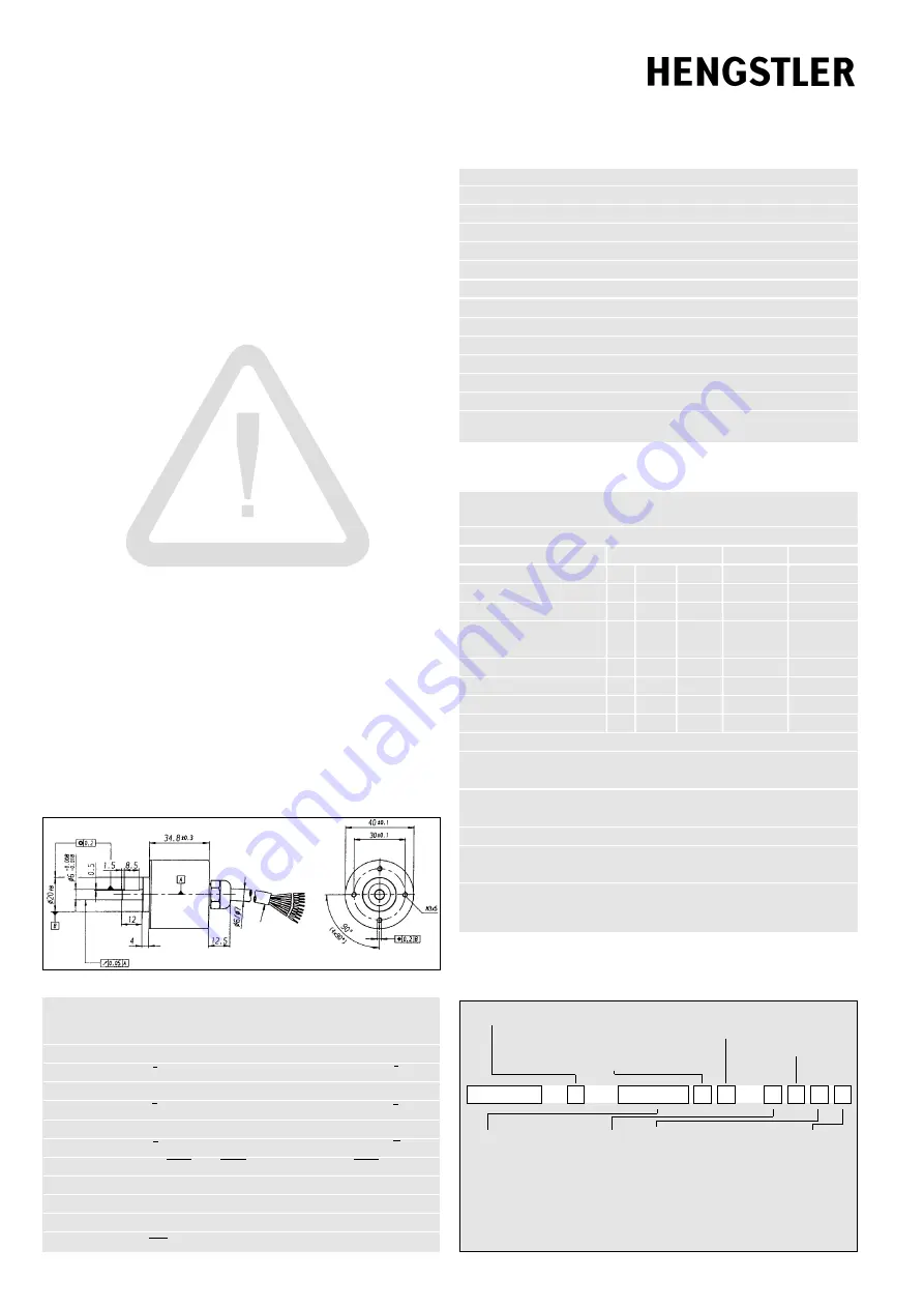
Dimensioned drawing


