background image


-

 56 -


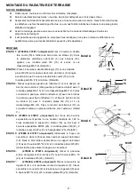
MONTAŻ 
 

KROK 1: 

tylko  272800 & 272817


Przykręć  tylny  panek 

obudowy  palnika  (3)  za  pomocą  4  krótkich  wkrętów 
dwustronnych  (16).  Zamocuj  zewnętrzną  osłonę 
grzejnika  (4)  za  pomocą  wkrętów  (16),  umieść 
podkładki płaskie Φ6 (15) i przykręć  nakrętki M6 (14).


Rys. detalu A) 

KROK 2: 

Wkręć do pokrywy obudowy palnika (3) 4 długie 

wkręty dwustronne (17) i umieść podkładkę płaską Φ6 
(15) (z przodu) oraz 2 krótkie wkręty dwustronne (16) i 
podkładkę płaską Φ6 (15) (z tyłu).

 Rys. detalu B) 

KROK 3: 

Naj

pierw umieść lewy panel reflektora

 (1) na pokrywie 

obudowy palnika (z lewej strony) i zamocuj go za 

pomocą 3 podkładek płaskich Φ6 (15) i 3 nakrętek M6 
(14).  Umieść

  prawy panel reflektora (2) tak, by 

pasowały  weń  bolce  lewego  panelu  reflektora  (1)  i 
zamocuj  go  do  obudowy  palnika  (3)  za  pomocą  3 
podkładek  płaskich Φ6  (15)  i  3  nakrętek  M6 

(14). 

Zamknij  środkową  obejmę  reflektora  grzejnego  za 
pomocą zacisku z tyłu (18).

 (Rys. detalu C)  

KROK 4: (tylko 272800 & 272817)


Otwory montażowe na kołki 

rozporowe  powinny  znajdować  się  na  wysokości 
minimalnie  ok.  1,48  m.  Zamocuj  uchwyt  montażowy 

palnika 

(19)  prawidłowo  do  ściany  za  pomocą  4 

kołków rozporowych M8*45 (20), 4 podkładek płaskich 
Φ8 (21), 4 podkładek sprężystych (22) i 4 śrub z łbem 
sześciokątnym (23).

 (Rys. detalu D).  

KROK 5: (tylko 272800 & 272817)

 Przetknij gumowy przewód 

przez  otwór  w  odgiętym  ramieniu  uchwytu  palnika


(19).  Zamocuj  skręcony  zespół  palnika  do  uchwytu


palnika 

(19)  za  pomocą


4  wkrętów  M5*12  (24)  i  4 

podkładek  płaskich  Φ5

  (25).  (Rys. detalu E).


Nie 

należy wyjmować pierścień gumowy


KROK 6: (tylko  272909 & 272916) 

Przykręć  tylny  panel 

obudowy (9) do podstawy (11) za pomocą 5 wkrętów 

M5x10 (24) i 5 

podkładek Φ5 (25).

 (Rys. detalu F) 

KROK 7: (tylko 272909 & 272916) 

Umieść  pokrywę  obudowy 

(8)  na  tylnym  panelu  obudowy  (9).  Skręć  pokrywę 
obudowy  z  tylnym  panelem  obudowy  za  pomocą 

wkrętów M5x12 (24) i 5 podkładek płaskich Φ5

 (25). 

(Rys. detalu G)


MONTAŻ GRZEJNIKA TARASOWEGO  


INSTRUKCJA MONTAŻU 


Wykaz wymaganych narzędzi: Śrubokręt Philips / Klucze nastawne / Klucze maszynowe


Roztwór do wykrywania nieszczelności: 1 część detergentu na 3 części wody


Najpierw odkręć wszystkie nakrętki i wkręty. Po zakończeniu montażu dokręć wszystkie złącza. 
Ułatwi Ci to pracę i zwiększy stabilność urządzenia.


Przed przystąpieniem do montażu upewnij się, że usunięte zostały wszystkie materiały 

opakowaniowe i ochronne. 


Mogą występować niewielkie różnice pomiędzy urządzeniami. Nie jest to oznaką niższej jakości, lecz 
wynikiem ciągłego wprowadzania usprawnień.


15  14 

16 

Detal A 

Detal D 

WALL 

22 

21 

23 

19 

20 

16 

Detal B 

14 

17 

Detal C 
Содержание 272800

Страница 1: ......

Страница 2: ...1...

Страница 3: ...GEN TERRASVERWARMER 3 ONDERDELENLIJST 4 MONTAGE TERRASVERWARMER 5 BEDIENINGSINSTRUCTIES 7 TESTEN OP LEKKAGES 7 EISEN AAN DE GASTOEVOER 8 BELANGRIJKE VEILIGHEIDSREGELS 9 ONDERHOUD 10 PROBLEEMOPSPORING...

Страница 4: ...eschadiging of excessieve slijtage zijn De vervangende slang moet voldoen aan de specificaties van de fabrikant Het apparaat moet v r gebruik en min 1x per jaar door een servicemonteur ge nspecteerd w...

Страница 5: ...bele kopbouten kort 6 4st ringen 6 en 4st dopschroeven M6 voor het achterpaneel v h branderscherm en het buitenste kachelscherm 4st dubbele kopbouten lang 6 en 4st ringen 6 onder voor 2st stiftbouten...

Страница 6: ...0 272817 Steek de rubberen slang door het gat van de gebogen kolom van de branderbeugel 19 Bevestig de afgemonteerde brandereenheid aan de branderbeugel 19 met 4 bouten M5 12 24 en 4 ringen 5 25 detai...

Страница 7: ...alleen 272909 272916 Bevestig de klep aan de behuizing zie afb 1 en detail afb J STAP 11 alleen 272909 272916 Bevestig 3 borgelementen aan het voetgedeelte detail afb J Gebruik spijkers of bouten om...

Страница 8: ...inuten om het gas te laten vervliegen Herhaal de stappen voor ontsteking van de waakvlam VERWARMER UITZETTEN Houd de knop ingedrukt draai hem naar rechts op OFF Sluit na gebruik de afsluiter van de ga...

Страница 9: ...de koperen pijpen voor aansluiting van de 272800 272817 dient min 5m te bedragen De diameter van de koperen pijpen is minimaal 15 mm alleen 272800 272817 Een veiligheidsvoorziening modelnr TYP420A mo...

Страница 10: ...evaarlijk zijn en is VERBODEN Kinderen en volwassenen moeten zich bewust zijn van de hoge temperaturen van de delen boven de kolom bij gebruik van de verwarmer Houd kinderen nauwlettend in de gaten al...

Страница 11: ...n verricht reparaties per omgaande SERVICE Raadpleeg uw lokale dealer over servicebeurten voor het apparaat en vervanging van onderdelen Servicebeurten mogen alleen door vakbekwaam personeel verricht...

Страница 12: ...ur 5 40 F Gasdruk is te laag Vervang de gasfles De buitentemperatuur is hoger dan 5 40 F en de gasfles is minder dan 25 vol Vervang de gasfles De toevoerslang is gebogen of geknikt Zorg dat de slang r...

Страница 13: ...13kW 13kW Gasverbruik 980g uur 1025g uur 980g uur Injectormaat 1 73mm 1 73mm 1 5mm 1 73mm 1 6mm Land van bestemming CH ES FR GB IE IT PT DK FI NL NO CH DE FR GB CH IE PT AT CH DE NL ES GB Serienr dat...

Страница 14: ...ierdoor onverlet Geef bij garantieclaims aan waar en wanneer het apparaat gekocht werd en toon uw aankoopbewijs bijv kassabon Vanwege ons beleid inzake continue productverbetering behouden wij ons het...

Страница 15: ...SAFETY WARNINGS 15 PART LIST 16 PATIO HEATER ASSEMBLY 17 OPERATING INSTRUCTIONS 19 LEAK TESTING 19 CONNECTING TO A GAS CYLINDER 20 IMPORTANT SAFETY RULES 21 MAINTENANCE 22 STORAGE 22 TROUBLESHOOTING...

Страница 16: ...evidence of excessive abrasion or wear or if the hose is damaged and that the replacement hose assembly shall be that specified by the manufacturer The heater should be inspected before use and at le...

Страница 17: ...ded bolts short 6 4pcs flat washers 6 and 4pcs cap screws M6 for rear panel of burner screen assembly and outer heater shield 4pcs double headed bolts long 6 and 4pcs flat washers 6 below in the front...

Страница 18: ...4pcs hex screws 23 Detail Abb D STEP 5 272800 272817 only Put rubber hose through the hole of bent post of burner bracket 19 Fix the finished burner assembly on the burner bracket 19 with 4pcs bolts...

Страница 19: ...bb I SETP 10 272909 272916 only Fix the door to housing See Figure 1 and Detail Abb J SETP 11 272909 272916 only Attach 3pcs stands to the base Detail Abb J Use nails or raw bolts to fix the base to t...

Страница 20: ...dissipate before attempting to re light pilot Repeat the Lighting steps TO EXTINGUISH Hold knob depressed turn the knob clockwise to OFF Close the valve of the gas cylinder or the regulator after use...

Страница 21: ...n of 272800 272817 shall be at least 5m The Diameter of the copper tubing is at least 15mm 272800 272817 only A safety device Model No TYP420A must be used to connect copper tubing and regulator The s...

Страница 22: ...s should be aware of the high operating temperatures of areas above the post when operating this heater Children should be carefully supervised when in the vicinity of the heater NEVER hang anything i...

Страница 23: ...heck the corroded areas and repair them promptly SERVICING Please consult your local dealer for servicing this appliance and replacement of its parts The servicing of the appliance shall be carried ou...

Страница 24: ...te Do not operate heater below 5 40 F Gas pressure is low Replace gas cylinder Outdoor temperature is greater than 5 40 F and tank is less than 25 full Replace gas cylinder Supply hose is bent or kink...

Страница 25: ...13kW 13kW 13kW 13kW Gas Consumption 980g h 1025g h 980g h Inject Size 1 73mm 1 73mm 1 5mm 1 73mm 1 6mm Country of Destination CH ES FR GB IE IT PT DK FI NL NO CH DE FR GB CH IE PT AT CH DE NL ES GB Se...

Страница 26: ...statutory rights are not affected If it s under guarantee state where and when it was bought and include proof of purchase e g till receipt In line with our policy of continuous product development w...

Страница 27: ...RHEITSHINWEISE F R SICHEREN BETRIEB DES GASHEIZSTRAHLERS 27 ST CKLISTE 28 ZUSAMMENBAU DES GASHEIZSTRAHLERS 29 BETRIEBSANWEISUNGEN 32 LECKPR FUNG 32 WARTUNG 35 LAGERUNG 35 ST RUNGSBEHEBUNG 36 TECHNISCH...

Страница 28: ...em n chsten Betrieb Leck reparieren Einmal monatlich und nach jedem Gasflaschenwechsel Flexschlauch und Rohrleitungen berpr fen Tauschen Sie Flexschlauch oder Rohrleitungen nach einem Jahr aus Tausche...

Страница 29: ...erschrauben M6 f r R ckwand der Brennerschirm Baugruppe und dem u eren Heizbrenner Schutzschild 4 Stiftschrauben lang 6 mm Durchmesser und 4 Unterlegscheiben 6 mm Durchmesser f r untere Vorderseite 2...

Страница 30: ...1 Linkes W rmereflektorblech 1 2 Rechtes W rmereflektorblech 1 3 Brennerschirm Baugruppe 1 4 u eres Heizbrenner Schutzschild 1 5 Unterer Heizbrenneraufsatz 1 6 Untere Schirmzylinder Baugruppe 1 7 Haup...

Страница 31: ...18 mittig ber die hintere Lasche befestigen Position C SCHRITT 4 nur Typ 272800 272817 Die Mindesth he der Befestigungsl cher f r die Ankerbolzen betr gt 1 48 m Heizbrennerhalterung 19 sicher mit den...

Страница 32: ...09 272916 T r am Geh use befestigen Siehe Abb 1 und Position J SCHRITT 11 nur Typ 272909 272916 3 St nderbauteile am Ger tefu befestigen Position J Den Ger tefu mit einfachen Bolzen oder N geln auf de...

Страница 33: ...Hinweis Der Heizbrenner kann beim ersten Z nden etwas laut sein Um eine berm ige Ger uschentwicklung vom Heizbrenner zu vermeiden drehen Sie den Gasreglerknopf wieder auf Pilotflammenposition Drehen S...

Страница 34: ...n Je nach L nderbestimmungen muss ein anderer zugelassener Flexschlauch eingebaut werden Die L nge des Flexschlauches betr gt wie folgt F r die Typen 272800 272817 0 45 0 8m F r die Typen 272909 27291...

Страница 35: ...des Gasheizstrahlers befindliche Kinder m ssen sorgf ltig beaufsichtigt werden NIEMALS an diesem Gasheizstrahler Gegenst nde aller Art wie Kleidung oder andere entflammbare Dinge aufh ngen NIEMALS di...

Страница 36: ...r Kleinere Partikel k nnen mit Druckluft herausgeblasen werden Kohlenstoffablagerungen stellen eine Brandgefahr dar Bei Kohlenstoffablagerungen m ssen Heizbrenner und Heizstrahleraufsatz mit warmem Se...

Страница 37: ...eitigen Verbindung zwischen Gasventil und Pilotflammenbaugruppe ist lose Verbindung wieder festziehen und Leckpr fung ausf hren Thermoelement ist defekt Thermoelement austauschen Heizbrenner z ndet ni...

Страница 38: ...m 1 73 mm 1 5 mm 1 73 mm 1 6 mm Bestimmungsland CH ES FR GB IE IT PT DK FI NL NO CH DE FR GB CH IE PT AT CH DE NL ES GB Seriennr und Datumscode Warnhinweis Vor Gebrauch des Gasheizstrahlers alle Anwei...

Страница 39: ...senbon Im Rahmen unserer kontinuierlichen Produktverbesserungsbestrebungen behalten wir uns ohne vorherige Ank ndigung das Recht auf nderungen an Produkt Verpackung und Dokumentationsinhalten vor ENTS...

Страница 40: ...ERRASSE 40 NOMENCLATURE DES PI CES 41 MONTAGE DU RADIATEUR DE TERRASSE 42 MODE D EMPLOI 44 CONTR LE DES FUITES 44 BRANCHEMENT DE LA BOUTEILLE DE GAZ 45 CONSIGNES DE S CURIT IMPORTANTES 47 ENTRETIEN 48...

Страница 41: ...t tre remplac avant de faire fonctionner l appareil en cas de signe d abrasion ou d usure excessive ou s il est endommag et le syst me de remplacement doit tre celui pr cis par le fabricant Le radiate...

Страница 42: ...PI CES DE MONTAGE FOURNIES 4 boulons double t te courts 6 4 rondelles plates 6 et 4 vis d assemblage M6 pour le panneau arri re du bloc cran du br leur et de la protection calorifique ext rieure 4 bo...

Страница 43: ...PE 5 272800 272817 uniquement Introduisez le boyau en caoutchouc dans l orifice du bras coud du support du br leur 19 Fixez le bloc br leur assembl sur le support du br leur 19 avec 4 boulons M5 12 24...

Страница 44: ...25 D tail I TAPE 10 272909 272916 uniquement Fixez la porte au logement Voir Figure 1 et D tail J TAPE 11 272909 272916 uniquement Fixez 3 pieds la base D tail J Utilisez des clous ou des boulons d an...

Страница 45: ...mment lors du premier allumage Pour liminer tout bruit excessif tournez le bouton de r glage sur la position Pilot Puis r glez le bouton sur le niveau de chaleur d sir R ALLUMAGE Placez le bouton de r...

Страница 46: ...eur du flexible utiliser 272800 272817 0 45 0 8m 272909 272916 1 3 m Le montage des tubes doit tre effectu par une personne qualifi e du pays de destination Les tubes en cuivre de 272800 272817 doiven...

Страница 47: ...es de cuivre du flexible au dispositif de s curit du r gulateur l arriv e de gaz Dispositif de s curit n TYP420A Tubes en cuivre conforme la norme EN1507 d au moins 15 mm longueur d au moins 5 m Branc...

Страница 48: ...ue certaines zones de l appareil situ es au dessus du poteau peuvent atteindre une haute temp rature lorsque l appareil fonctionne Les jeunes enfants et les animaux domestiques doivent tre surveill s...

Страница 49: ...corrosion appara t plus rapidement qu en temps normal Inspectez fr quemment l appareil et r parez sans d lai toute zone ventuelle de corrosion R PARATION Veuillez consulter votre revendeur local pour...

Страница 50: ...teur moins de 5 C Faible pression de gaz Remplacez la bouteille de gaz La temp rature ext rieure est sup rieure 5 C et la bouteille est remplie moins de 25 Remplacez la bouteille de gaz Le flexible d...

Страница 51: ...3 kW Consommation de gaz 980 g h 1025 g h 980 g h Taille de l injecteur 1 73 mm 1 73 mm 1 5 mm 1 73 mm 1 6 mm Pays de destination CH ES FR GB IE IT PT DK FI NL NO CH DE FR GB CH IE PT AT CH DE NL ES G...

Страница 52: ...fect s Si l appareil se trouve sous garantie pr cisez l endroit o il a t achet et joignez votre preuve d achat ticket de caisse par exemple Conform ment notre politique de d veloppement continu de pro...

Страница 53: ...A DOTYCZ CE BEZPIECZE STWA U YTKOWANIA 53 WYKAZ CZ CI 54 CZ CI GRZEJNIKA TARASOWEGO 55 INSTRUKCJA MONTA U 56 INSTRUKCJA OBS UGI 58 POD CZANIE BUTLI Z GAZEM 59 KONSERWACJA 61 USUWANIE USTEREK 62 DANE T...

Страница 54: ...zowy nale y co roku wymienia W przypadku stwierdzenia nadmiernego zu ycia ciernego przewodu gazowego b d jego uszkodzenia nale y przed uruchomieniem urz dzenia wymieni przew d gazowy na taki sam przew...

Страница 55: ...trznej os ony grzejnika 4 wkr ty dwustronne d ugie 6 i 4 podk adki p askie 6 u do u z przodu 2 wkr ty dwustronne kr tkie 6 i 2 podk adki p askie 6 u do u z ty u 6 podk adek p askich 6 u g ry i 6 nakr...

Страница 56: ...obudowy 1 10 Drzwi 1 11 Podstawa 1 12 K ko 2 13 Zawias 1 14 Nakr tka M6 14 15 Podk adka p aska 6 20 16 Wkr t dwustronny kr tki 6 17 Wkr t dwustronny d ugi 4 18 Obejma reflektora 1 19 Uchwyt monta owy...

Страница 57: ...1 4 podk adek spr ystych 22 i 4 rub z bem sze ciok tnym 23 Rys detalu D KROK 5 tylko 272800 272817 Przetknij gumowy przew d przez otw r w odgi tym ramieniu uchwytu palnika 19 Zamocuj skr cony zesp pal...

Страница 58: ...K 10 tylko 272909 272916 Zamocuj drzwi do obudowy Patrz Rysunek 1 i Rys detalu J KROK 11 tylko 272909 272916 Przytwierd 3 elementy stojaka do podstawy Rys detalu J Zamocuj podstaw do pod o a za pomoc...

Страница 59: ...admierny ha as powodowany przez palnik obr pokr t o regulacyjne do pozycji PILOT po czym obr je do pozycji odpowiadaj cej po danemu poziomowi ogrzewania PONOWNE ZAPALANIE Obr pokr t o regulacyjne do u...

Страница 60: ...272916 1 3 m Monta rurowego przewodu gazowego powinien zosta wykonany przez wykwalifikowanego fachowca z kraju przeznaczenia Miedziany przew d rurowy grzejnika 272800 272817 powinien spe nia odpowiedn...

Страница 61: ...znie pilnowa dzieci znajduj cych si w blisko ci grzejnika Nie wolno NIGDY wiesza niczego na grzejniku w tym odzie y ani innych palnych przedmiot w NIE WOLNO u ywa grzejnika dop ki nie zostanie on ca k...

Страница 62: ...ego cz ci prosz kontaktowa si z lokalnym dostawc Obs uga serwisowa tego urz dzenia powinna by wykonywana wy cznie przez pracownik w autoryzowanego serwisu Ostrze enie nie wolno u ywa do tego urz dzeni...

Страница 63: ...p poni ej 5 40 F Niskie ci nienie gazu Wymie butl gazow na now Temepratura na zewn trz przekracza 5 40 F a butla jest nape niona w mniej ni 25 Wymie butl gazow na now Przew d gazowy jest zgi ty lub za...

Страница 64: ...e gazu 980 g h 1025 g h 980 g h Wielko wtrysku 1 73 mm 1 73 mm 1 5 mm 1 73 mm 1 6 mm Kraj przeznaczenia CH ES FR GB IE IT PT DK FI NL NO CH DE FR GB CH IE PT AT CH DE NL ES GB Nr serii i kod daty Ostr...

Страница 65: ...bez uszczerbku dla praw przys uguj cych nabywcy Prawa wynikaj ce z gwarancji przys uguj za podaniem miejsca i daty zakupu i okazaniem dowodu kupna np paragonu Zgodnie z nasz polityk ci g ego rozwoju p...

Страница 66: ...Hendi Austria GmbH Austria Gewerbegebiet Ehring 15 5112 Lamprechtshausen Austria Tel 43 0 6235 200 10 0 Fax 43 0 6235 200 100 20 www hendi austria com office hendi austria com Hendi Polska Spolka z o...

Отзывы: