

ELECTRICAL CONNECTIONS
1. All wiring, fusing, and grounding must comply with National Electrical codes.
2. To determine proper rotation and voltage connections, refer to the information and diagram on the nameplate, separate
connection plate, or decal. If the plate or decal has been removed, contact the manufacturer for assistance.
3. Use the proper size of line current protection and motor controls as required by the National Electrical Code, and local codes.
Recommended use is 125% of full load amps as shown on the nameplate for motors with 40 degrees Celsius ambient and
a service factor over 1.0. Recommended use is 115% of full load amps as shown on the nameplate for all other motors.
Do not use protection with larger capacities than recommended. Three phase motors must have all three phases protected.
WARNING
!
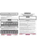
P1 LINE 1
RED
P2 INSULATE
ORANGE
BLACK
WHITE LINE 2
YELLOW
L
O
W
V
O
L
T
H
I
G
H
V
O
L
T
P1 LINE 1
P2 INSULATE
RED
ORANGE INSULATE
WHITE
BLACK LINE 2
YELLOW
Rotation CCW - OPE To Reverse Either
Voltage Interchange Black and Red Leads
CHANGING ROTATION
1. Keep hands and clothing away from rotating parts.
2. Before the motor is coupled to the load, determine proper rotation.
3. Check rotation by jogging or bumping. Apply power to the motor leads for a short period of time, enough to just get motor
shaft to rotate a slight amount to observe shaft rotating direction.
4. Three phase - interchange any (2) of the three (3) line leads. Single phase - reconnect per the connection diagram on
the motor
Wire Size for 115 & 230 Volt Single Phase Circuits
Distance - Motor to Fuse or Meter Box - Feet
Motor
HP
100 Ft.
200 Ft.
300 Ft.
500 Ft.
115V
230V
115V
230V
115V
230V
115V
230V
1/4
#14
#14
#10
#12
#8
#10
#6
#8
1/3
#12
#14
#10
#12
#6
#10
#4
#8
1/2
#10
#12
#8
#10
#6
#8
#4
#6
3/4
#10
#12
#6
#10
#4
#8
#2
#6
1
#8
#10
#6
#8
#4
#6
#4
1 1/2
#4
#10
#0
#8
#6
#4
2
#8
#6
#4
#2
3
#8
#6
#4
#2
5
#6
#4
#2
#0
Disconnect power before working on motor driven equipment
Motors with automatic thermal protectors will automatically restart when the protector cools. Do not use motors with
automatic thermal protectors in applications where automatic restart will be hazardous to personnel or equipment.
Motors with manual thermal protectors may start unexpectedly after the protector trips. If manual protector trips. disconnect
motor from power line. After protector cools (fi ve minutes or more) it can be reset and power may be applied to the motor.
THERMAL PROTECTOR INFORMATION
The nameplate will indicate one of the following:
1. Motor is thermally protected
2. Motor is provided with overheat protective device.
For Example:
1. Motors without thermal protection will have nothing stamped on nameplate about thermal protection.
2. Motors equipped with built-in thermal protection have “THERMALLY PROTECTED” stamped on the nameplate. Thermal
protectors open the motor circuit electrically when the motor overheats or is overloaded. The protector cannot be reset until
the motor cools. If the protector is automatic, it will reset itself, If the protector is manual, press the red button to reset.
3. Motors that are provided with overheat protective device that does not open the motor circuit directly will indicate “ WITH
OVERHEAT PROTECTIVE DEVICE:. See motor connection diagram for details.
REDUCED VOLTAGE STARTING
Motors used on reduced voltage starting, should be carefully selected based upon power supply limitations and driven load
requirements. The motors starting torque will be reduced when using reduced voltage starting. The elapsed time on the start
step should be kept as short as possible and should not exceed 5 seconds. It is recommended that this time be limited to 2
seconds. Refer to the manufacturer for application assistance.
OPERATION
BEFORE INITIAL STARTING
1. If a motor has become damp in shipment or in storage, measure the insulation resistance of the stator winding.
Minimum Insulation Resistance = 5 Megaohlms ( use 500 volt megger)
Do not attempt to run motor if the insulation resistance is below this value. Have the motor inspected, dried and/ or cleaned.
Contact a qualifi ed motor repair shop.
2. See that voltage and frequency stamped on motor and control nameplates correspond with that of the power line.
3. Check all connections to the motor and control with the wiring diagram.
4. Be sure rotor turns freely when disconnected from the load. Any foreign matter in the air gap should be removed.
5. Leave the motor disconnected from the load for the initial start ( see following instructions). Check for proper rotation.
Check for correct voltage ( 10% of nameplate value) ant that is balanced within 1% at the motor terminals. After the
machine is coupled to the load, check that the nameplate amps are not exceeded. Recheck the voltage level and balance
under load per the above guidelines.
Shut down the motor if the above parameters are not met or if any other noise or vibration disturbances are present. Consult
NEMA guidelines or the equipment manufacturer if any questions exist before operating equipment.
ALLOWABLE VOLTAGE AND FREQUENCY RANGE
If voltage and frequency are within the following range, motors will operate , but with somewhat different characteristics than
obtained with correct nameplate values.
1. Voltage : Within 10% above or below the value stamped on the nameplate. On three phase systems the voltage should be
balanced within 1%. A small voltage unbalance will cause a signifi cant current unbalance.
2. Frequency: Within 5% above or below the value stamped on the nameplate.
3. Voltage and Frequency together: Within 10% ( providing frequency above is less than 5%) above or below values stamped
on the nameplate.
CLEANLINESS
Keep both the interior and exterior of the motor free from dirt, water , oil and grease. Motors operating in dirty places should
be periodically disassembled and thoroughly cleaned.
NOTE
Motors should be disassembled only by an authorized service station
DO NOT disassemble hazardous duty motors, see warning below
CONDENSATION DRAIN PLUGS
All explosion proof and some totally enclosed motors are equipped with automatic drain plugs, they should be free of oil,
grease, paint, grit, and dirt so they don’t clog up. The drain system is designed for normal fl oor (feet down) mounting. For
other mounting positions, modifi cations of the drain system may be required, consult the manufacturer.
SERVICE
WARNING
!
1. Motors nameplated for hazardous locations should be disassembled only by the original equipment manufac-
turer or by a facility that is UL listed under UL’s category: “ Motors & Generators, Rebuilt for Use in Hazardous
Locations”.
2. Disconnect power before working on motor or driven equipment. Motors with automatic reset thermal protec-
tors will automatically restart when the protector cools. Do nor use motors with automatic reset thermal protec-
tors in applications where automatic restart will be hazardous to personnel or equipment.
CAUTION
!
Over Greasing bearings can cause premature bearing and / or motor failure. He amount of grease added should
be carefully controlled.