


2
2
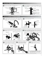
3
Place the wall finished wall, ensuring that the installation meets the
shown dimensions. /
Coloque el acabado final de pared,
asegurándose que la instalación cumpla con las medidas
mostradas.
4
Unscrew the stud and the set screw with the allen wrench
(included), remove the wall bracket and the escutcheon. /
Desenrosque el espárrago y el opresor con la llave allen
(incluida), retire el ancla y el chapetón.
5
Screw the stud to the water supply line. /
Enrosque el espárrago a
la línea de alimentación.
escutcheon
chapetón
stud
espárrago
wall bracket
ancla
set screw
opresor
stud
espárrago
hole for wiring
orificio para
cableado
Insert the wall bracket to wall or stainless steel sink depending on
the case. /
Inserte el ancla al muro o mueble de acero inoxidable
según sea el caso.
6
Insert the wires through the holes for anchor wiring, insert the
escutcheon with gasket and the faucet, screw the set screw to
secure the faucet with the included wrench. /
Introduzca los cables
por los barrenos para cableado del ancla, inserte el chapetón con
empaque y la salida, enrosque el opresor para fijar la salida con la
llave incluida.
7
Ø 5/16” drill
barreno Ø 5/16”
Ø
”
7/8 drill
barreno
Ø 7/8”
0 75”
,
2 cm
Lateral view
Vista lateral
Ø 13/64” drill
barreno
Ø 13/64”
stainless steel sink
mueble de acero
inoxidable
Installation to wall
Instalación a muro.
Installation to back of stainless-steel sink
Instalación a mueble de acero inoxidable
con respaldo.
3”
7,5 cm
back
respaldo
lead anchor
taquete de plomo
stud (included)
1/2”-14 NPSM
espárrago (incluido)
1/2”-14 NPSM
0 75”
,
minimum
2 cm mínimo
holes for wiring
barrenos para
cableado
red/black wire
cable rojo/negro
gray wire
cable gris
wall bracket
ancla
stud
espárrago
alignment
plane
plano para
alineación
water supply line
línea de alimentación
set screw
opresor
8
elecronic module
(included)
módulo electrónico
(incluido)
Place the electronic module (included),
mark and drill with
Ø 1/4"
drill bit. /
P r e s e n t e e l m ó d u l o e l e c t r ó n i c o
(incluido), marque y barrene con broca
de
Ø 1/4"
.
9
lag screw
pija
10
3"
(7,5 cm)
12”
(30 cm)
4”
10 cm
supply line
línea de alimentación
4”
10 cm
supply line for faucet
línea de alimentación
para salida
finished wall
pared con acabado final
0,4” mínimo
1 cm minimum
stud
espárrago
water supply line (not included)
línea de alimentación
(no incluida)
angle valve
válvula angular
½” piping (not included)
tubería de ½” (no incluida)
Groove the wall according to the dimensions shown. /
Ranure
el muro con las medidas que se muestran.
drain (drain piping)
desagüe (céspol)
PVC piping for sensor
wires (included)
tubería de PVC para
los cables del sensor (incluido)
PVC piping for
sensor wires (included)
tubería de PVC para
sensor (incluido)
1/2" NPT external
thread connector
conector de 1/2” NPT
cuerda exterior
PVC piping for
sensor wires (included)
tubería de PVC para
los cables del sensor (incluido)
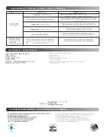
Purge the supply line by opening and
closing it. /
Purgue la línea de
alimentación abriéndola y cerrándola.
N
ote: Purge the water supply line before connecting
the hose. Remember to keep the supply line closed
until installation is finished. /
Nota: Purgue la línea de
suministro de agua antes de conectar la manguera.
Recuerde mantener el suministro de agua cerrado
hasta terminar con la instalación.
Insert the anchors (included) and
screw the lag screws (included). /
Inserte los taquetes (incluídos) y
enrosque con las pijas (incluídas).
anchor
taquete
finished wall
pared con acabado final


