


16
17
19
18
20
21
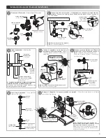
2
*A
tubería de alimentación
32 mm (
Ø 1¼”
) (no incluida)
feed pipe 32 mm (Ø 1 ¼")
(not included)
60 cm
(23,6”)
reducción campana de
Ø 32-25,4 mm
(1¼”-1”)
(no incluida)
bell reduction
Ø 32-25,4 mm (1 ¼"-1")
(not included)
cámara de aire
air chamber
tubo Ø 32 mm
(1¼”)
(no incluido)
tube Ø 32 mm (1 ¼ ")
(not included)
tubo Ø 25,4 mm
(1”)
(no
incluido) /
tube Ø 25,4 mm (1”)
(not included)
adaptador (incluido)
adapter (included)
Nota:
La tubería debe ser 32 mm (
Ø 1¼”)
desde la alimentación
.
Note:
The pipe should be (Ø 1 ¼") from supply.
Verificar que la dimensión
la necesaria para enroscar la llave
de retención con su chapetón,
hasta el paño de la pared. /
*A
sea
Check
that the dimension A is the
necessary to screw key retention
withescutcheon cloth to the wall.
Comp
entes el
odu to
/ P odu t C mpo
nts
on
d
Pr
c
r
c
o
ne
2
3
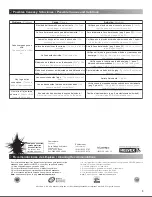
No. DESCRIPCIÓN
DESCRIPTION
1 Cúpula Ciega Fluxómetro
Dome Blind Flushometer
2 Émbolo 1LPF
1LPF Plunger
3 Rondana Vulcanizada
Washer Vulcanized
4 Tapón Fluxómetro Doble Botón
Double Button Fluxmeter Cap
5 O´ring 2-118
O´ring 2-118
6 Chapetón
Escutcheon
7 Niple p/ Cableado Fluxómetro
Nipple f/ Wiring Flushometer
8 Dispositivo Electrónico Flux Baterías
Flux Bateries Electronic Device
9 Tubo Camisa
Shirt Tube
10 Anillo de Presión
Pressure Ring
11 O'ring 2-123
O'ring 2-123
12 Llave de Retención Armada
Holding Key Armed
13 Adaptador
Adapter
14 Tubo Camisa
Shirt Tube
15 Chapetón Llave de Retención
Holding Key Escutcheon
16 Dispositivo Electrónico Flux Baterías
Electronic Device Flux Batteries
17 Caja p/ Circuito Electrónico
Safe w/ Electronic Circuit
18 Fuente Alimentación Regulada
Regulated Power supply
19 Tapa p/ Circuito Electronico s/ Sensor
Cover w/ Electronic Circuit w/ sensor
20 Paquete de Tornillo 8-32 x 1-1/2"
Pack Screw 8-32 x 1-1/2"
21 Kit Llaves de Mantenimiento
Maintenance Kit Keys
No. DESCRIPCIÓN
DESCRIPTION
22
Rondana tuerca, tuerca de 32 mm, niple
recto reducción 32 - 19 mm, kit tuerca
19 mm c/rondanas y chapetón mingitorio
19 mm
Washer nut, 1 ¼" nut, 1 ¼" - ¾" straight
nipple reduction, ¾" setting kit nut with
washers and ¾" urinal escutcheon
Para spud de Ø 19 mm /
For Ø ¾” spud
Para spud de Ø 19 mm
For Ø ¾” spud
1
22
2
3
4
5
9
10
11
12
13
14
15
8
7
6
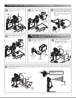
Ranure e instale la
tubería de conduit (no
incluida) conforme a
las medidas que se
especifican en la figura.
/ Slot and install
conduit pipe (not
included) according to
the measures specified
in the figure.
Antes de ranurar, presente la taza en la
instalación y mida.
/ Before grooving, this
cup and measure the installation.
6
4
5
Introduzca la caja de circuito dentro de la
perforación en el muro, fije con taquetes
y pijas (no incluidas).
/ Enter the circuit
box in the hole in the wall, set with
anchors and lag screws (not included).
caja para
circuito
circuit
ranura para
tubo conduit
slot conduit
Introduzca el cable de alimentación en
la caja para circuito.
/ Insert the power
cord into the box to circuit.
Coloque el acabado final y el
mingitorio. Barrene el orificio para el
cableado.
/ Put the finishing and the
urinal. Drill a hole for wiring.
adaptador
(incluido)
adapter (included)
tubo conduit para cable
de alimentación
conduit for power cable
cable de
alimentación
slot conduit
adaptador
(incluido)
adapter (included)
pared sin
acabado final
without wall
paso muro
Ø7/8” max.
Ø7/8" step wall
max.
adaptador
(incluido)
adapter (included)
pared sin
acabado final
without wall
12 cm
(4,7”)
2,5 cm
(1”)
5,5 cm
(2,1”)
2,5 cm
(1”)
2,5 cm
(1”)
12 cm
(4,7”)
9,5 cm
(3,8”)
13 cm
(5,2”)
25 cm
(10”)
21 cm
(8,3”)
Ranurado del Muro para
Eléctrica
la Instalación
Grooving the Wall for Electrical
Installation
I sta ación
ener l
Ge
ral ns ll tion
n
l
G
a
/
ne
I
ta a


