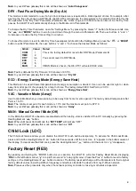
14
Touch Sensitivity
Parameter 06
(“tCH”) –
Touch Sensor Sensitivity Threshold
This Parameter allows the device Touch Button Sensitivity Threshold to be adjusted from level 1 (low sensitivity) to 10
(high sensitivity). The factory default value is 6.
Note:
Setting the sensitivity too high can lead to false touch detection. We recommend not changing this Parameter
unless there is a special need to do so.
Input & Ouput Configurations
Parameter 07
(“ГEL”) –
Relay output mode (NO / NC)
This Parameter determines the type of load connected to the device relay output. The output type can be NO
–
normal
open (no contact/voltage switch the load OFF) or NC - normal close (output is contacted / there is a voltage to switch
the load OFF). Choose the value 0 if NO contact type is required or value 1 if NC type is required.
The factory default value is 0.
Parameter 08
(“In1”) –
External Input Mode
The HE-HT01 can be connected to the dry output contacts of an external device (i.e. security system) to control the
Thermostat operating modes depending on the state of the external device.
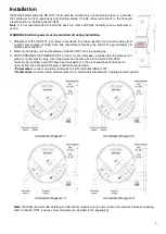
See Connection Diagrams on page 5 of this manual.
Note:
In case of using “
Connection Diagram 3 or 4
”, it is MANDATORY to connect S1 terminal to the same wire
connected
to terminal N on the device (labeled as “IN”) through dry contacts of an external device (like wall switch).
If Parameter value = 0 no action will be taken (the input state changes will be ignored by the Thermostat logic).
If Parameter value = 1
the external input will operate in “Toggle Switch” mode: if the external input is shorted (with Sx or
N) the Thermostat switches to the operating mode selected in the Parameter 09 and switches to MAN mode with IDLE
state (OFF) when the external input is open (released).
I
f Parameter value = 2
the external input will operate in “Toggle Switch Reverse” mode: if the external input is shorted the
Thermostat switches to MAN mode with IDLE state (OFF) and switches to the operating mode selected in the Parameter
09 when the input is open.
I
f Parameter value = 3
the external input will operate in “Push Button (Momentary Switch)” mode: each press of button
(shorten of the input) will consistently change the mode to mode selected in the Parameter 09 then to MAN mode with
IDLE state.
Note:
The
Mode switch is blocked when the Source Sensor (Parameter 11) is:
“t”
(value = 5),
“t
A
”
(value = 6) or
“t
F
”
(value
= 7). Factory default value is 0.
Parameter 09
(“In2”) –
Operating Mode for External Input Action
This Parameter allows selection of which Operating Mode the HE-HT01 should revert to if the external input S1 is short-
circuited. 1 = COM, 2 = TIME, 3 = DRY, 4 = ECO, 5 = VAC, 6 = MAN mode with IDLE (Off) state. Factory default value
is 6.
Parameter 10
(“FSr”) –
Floor Sensor Resistance
If the external floor NTC
temperature sensor is used it is necessary to select the correct resistance value in Ohms (Ω) of
the sensor. The selection range is 1 to 100 kiloOhms (kΩ). One 10kΩ NTC floor temperature sensor is included in the
HE-HT01 package with a 3-meter connection w
ire. The factory default value is 10kΩ.
Note:
If the floor sensor is disconnected or damaged “
–
–
” will be shown on the LCD display under the FLOOR TEMP
label.
Temperature Configurations
Parameter 11
(“SEn”) –
Source Sensor
The HE-HT01 has seven
Regulation Modes based on different sensors values. Use the Plus “+” and Minus “–” buttons to
choose follow modes:
Value through
Z-Wave
Value on
Screen
Source Sensor
1
2
3
4
5
6
7
A
AF
F
FA
t
tA
tF
Air sensor
Air Floor sensor
Floor sensor
Floor Air sensor
Time regulator
Time reg Air sensor
Time reg Floor sensor


