


4 Control Unit KRONOS 20
KRONOS 20
19
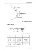
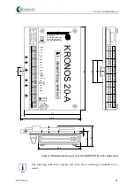
4.1.2
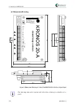
Inputs and Outputs
All inputs and outputs are reverse polarity protected and short-circuit-proof against bat-
tery plus and minus.
Temperature input (terminal 4)
for PT1000 / Ni1000 sensors
Tolerances: < ±2°C at 0°C to 130°C,
otherwise < ±4°C
Reference voltage for P-/T sensor
U
ref
= 5 V ±1 %, I
ref
< 30 mA
(terminal 6)
Closed loop input (terminal 7)
U = 0..5 V, R
e
= 100 k
Ω
, f
g
= 15 Hz
or I = 4..20 mA
Digital input (terminal 9)
U
0
< 2 V, U
1
> 6.5 V, R
pd
= 100 k
Ω
Digital input engine stop
U
0
< 2 V, U
1
> 6.0 V R
pd
= 4.75 k
Ω
(terminal 11)
or R
pu
= 4.75 k
Ω
or R
pd
= 150 k
Ω
Speed input (terminal 13)
for inductive sensors, with
f
i
= 25 to 9000 Hz, U
i
= 0.5 to 30 V AC
MAP pressure input (terminal 16)
U = 0..5 V, R
e
= 100 k
Ω
, f
g
= 15 Hz
Control outputs for gas valve
I
sink
< 0.3 A, U
rest
< 1.0 V, I
leak
< 0.1 mA
(terminals 1 and 2)
R
pu
= 4.75 k
Ω
or R
pu
=
∞
, low-side switching
Digital output error lamp
I
sink
< 0.3 A, U
rest
< 1.0 V, I
leak
< 0.1 mA
(terminal 10)
R
pu
= 4.75 k
Ω
or R
pu
=
∞
, low-side switching
Serial interface ISO 9141,
variable from 2.4 kbit/s to 57.6 kbit/s
Standard 9.6 kbit/s
CAN bus (terminals H and L)
HEINZMANN-CAN or customer specification
Содержание E-LES 30
Страница 2: ......
Страница 8: ......
Страница 104: ...17 Order Form for KRONOS Systems 96 KRONOS 20 17 Order Form for KRONOS Systems...


