background image

INSTALLATION INSTRUCTIONS

Fan Coils: FEM4X, FEM4P, REM4X, FXM4X

10

496 01 5503 02

Specifications  are subject to change without notice.

To change motor speeds disconnect the BLUE fan lead from

motor connector terminal #2 (factory default position) and

move to desired speed tap; 1, 2, 3, or 5 (see 

Figure 14)

.

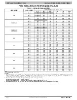
Speed taps 1, 2, and 3 have a 90 second blower off time

delay pre

programmed into the motor. Speed tap 4 is used

for electric heat only (with 0 second blower time delay) and

the WHITE wire should remain on tap 4. Speed tap 5 is used

for high static applications, but has a 0 second blower time

delay pre

programmed into the motor (see Airflow

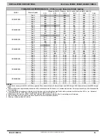
Performance Tables for actual CFM for each tap). Also, see

Figure 14

 for motor speed selection location.

NOTE:

 In low static applications, lower motor speed tap should

be used to reduce possibility of water being blown off coil.

REFRIGERANT TUBING

Refrigerant Tubing Connection and Evacuation

Use accessory tubing package or field

supplied tubing of

refrigerant grade. Suction tube must be insulated. Do not use

damaged, dirty, or contaminated tubing because it may plug

refrigerant flow

control device. ALWAYS evacuate the coil

and field

supplied tubing to 500 microns before opening

outdoor unit service valves.
Units have sweat suction and liquid tube connections. Make

suction tube connection first.

1. Cut tubing to correct length.
2. Insert tube into sweat connection on unit until it

bottoms.

3. Braze connection using silver bearing or non

silver

bearing brazing materials. Do not use solder (materials

which melt below 800

_

F / 427

_

C). Consult local code

requirements.

4. Evacuate coil and tubing system to 500 microns using

deep vacuum method.

Size and install refrigerant lines according to information

provided with outdoor unit. Route refrigerant lines to the fan

coil in a manner that will not obstruct service access to the

unit or removal of the filter.

Figure 14

Motor Speed Selection

1   2   3   4   5

Speed Taps may be located on motor,

or on plug close to motor.

L11S018

CL

G
N

1   2   3   4   5

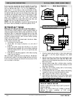
1. Find the liquid tube grommet in the small

parts bag

and slide it onto the liquid refrigerant line (field

line

set).

2. Remove the lower door. Remove the tubing plate (with

suction tube grommet) and slide the plate with

grommet onto the refrigerant lines (field line

set), away

from braze joints.

3. Remove rubber plugs from coil stubs using a pulling

and twisting motion. Hold coil stubs steady to avoid

bending or distorting.

4. Wrap TXV and nearby tubing with a heat

sinking

material such as a wet cloth.

5. Fit refrigerant lines into coil stubs. Wrap a heat sinking

material such as a wet cloth behind braze joints.

6. Braze using a Sil

Fos or Phos

copper alloy.

7. After brazing, allow joints to cool. Slide tubing plate

back into place and position grommets around suction

and liquid tubes to ensure air seal.

PRODUCT DAMAGE HAZARD

Failure to follow this caution may result in product or

property damage.
Wrap a wet cloth around rear of fitting to prevent

damage to piston assembly or TXV and

factory

made joints

.

CAUTION

!
Содержание FEM4P

Страница 1: ...in the following manner The signal word CAUTION is used throughout this manual in the following manner Signal Words on Product Labeling Signal words are used in combination with colors and or picture...

Страница 2: ...ly duct work NOTE If the door gasket is damaged or missing the unit may not meet the ASHRAE 193 standard for cabinet air leakage Contact your supplier and order kit 1191140 Nuisance sweating may occur...

Страница 3: ...REM36 17 432mm FXM30 19 483mm B MODULAR UNITS FEM4X6000B REM4X6000B and FXM4X4800 6000 fan coils are two piece modular units This allows for modular units to be disassembled and components moved sepa...

Страница 4: ...kaged with accessory kit See Product Specification literature for kit part numbers During the conversion process remove the plastic cap covering the vertical drains only and discard Remove the plug fr...

Страница 5: ...fitting panel refer to Figure 5 2 Remove coil mounting screw securing coil assembly to right side casing flange 3 Remove coil assembly 4 Lay fan coil unit on its right side and reinstall coil assembly...

Страница 6: ...ghs C and install on opposite tube sheets f Install hose onto plastic spout 7 Install horizontal pan on right side of coil assembly 8 Slide coil assembly into casing Be sure coil bracket on each corne...

Страница 7: ...NST WALL 1 8 3mm INCH THICK ANGLE MOUNTING BRACKET TYPICAL BOTH SIDES SECURE FAN COIL TO STRUCTURE UNIT AWAY FROM WALL PIPE STRAP SECURE UNIT TO FLOOR ANGLE BRACKET OR PIPE STRAP 4 102mm MAX 4 102mm M...

Страница 8: ...rmed until the main disconnect switch remote to the unit is turned off A LINE VOLTAGE CONNECTIONS Fan Coils installed without electric heat require the use of a factory authorized Power Plug Kit acces...

Страница 9: ...uninterrupted or unbroken ground in order to minimize potential for personal injury or death if an electrical fault should occur The ground may consist of electrical wire or metal conduit when instal...

Страница 10: ...it bottoms 3 Braze connection using silver bearing or non silver bearing brazing materials Do not use solder materials which melt below 800_F 427_C Consult local code requirements 4 Evacuate coil and...

Страница 11: ...equired Consult outdoor unit pre sale literature for start assist kit part number Figure 15 Refrigerant Flow Control Device TEFLON SEAL BRASS HEX NUT STRAINER PISTON RETAINER BRASS HEX BODY DISTRIBUTO...

Страница 12: ...w running traps are inadequate and DO NOT allow proper condensate drainage refer to Figure 17 Figure 16 Recommended Condensate Trap 2 MIN 51mm 2 MIN 51mm UNIT Figure 17 Insufficient Condensate Trap DO...

Страница 13: ...r motor is de energized and stops E ELECTRIC HEAT OR EMERGENCY HEAT MODE Thermostat closes R to W W energizes electric heat relay s which completes circuit to heater element s W also energizes the ind...

Страница 14: ...4200 Tap 5 1560 1544 1507 1464 1424 1358 Tap 4 1419 1397 1358 1320 1279 1239 Tap 3 1419 1397 1358 1320 1279 1239 Tap 2 1249 1220 1184 1142 1093 1052 Tap 1 1242 1205 1158 1110 1069 1026 4800 Tap 5 1743...

Страница 15: ...1294 1245 Tap 2 1257 1226 1191 1141 1090 1033 Tap 1 1237 1206 1160 1121 1070 1013 FXM4X4800 Tap 5 1757 1725 1693 1653 1614 1576 Tap 4 1664 1626 1593 1552 1517 1477 Tap 3 1664 1626 1593 1552 1517 1477...

Страница 16: ...049 0 059 FXM4X24 0 016 0 027 0 038 0 049 0 059 30 0 049 0 059 0 070 0 080 36 0 070 0 080 0 090 0 099 FXM4X36 0 055 0 064 0 073 0 081 42 0 049 0 056 0 063 0 070 48 0 063 0 070 0 076 0 083 0 090 FXM4X...

Страница 17: ...ere POE oils may cause damage to certain plastics and roofing materials Vacuum pumps will not remove moisture from oil A liquid line filter drier is required on every unit Do not use liquid line filte...

Отзывы: