Installation
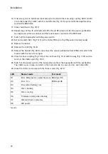
16. If necessary, mix an additional small amount of coolant in the measuring cup (Fig. 68/1) and fill
it into the funnel (Fig. 68/2) with the shutoff valve (Fig. 72/1) opened until the liquid level has
reached the MAX mark.
17. Close shutoff valve (Fig. 72/1).
18. Repeat steps 12 thru 15 until both red LEDs H1 and H2 remain lit after the service pushbutton
was kept pressed for one minute and the level remains constant at the MAX mark.
19. Switch off the Suprasetter with the power switch.
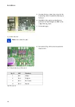
20. Set microswitch S2-3 (Fig. 70/3) on the chiller PCB up to the ON position (normal mode).
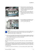
21. Remove the funnel.
22. Remove the cloth (Fig. 72/2).
23. Remove the bracket (Fig. 68/3), disconnect the service pushbutton from X158 and reattach the
bracket with the two screws again.
24. Close the hose coupling (Fig. 71/4) of the vent hose (Fig. 71/2) with the plug (Fig. 71/5) and fas-
ten it on the chiller again (Fig. 71/3).
25. Switch on the power switch of the Suprasetter and boot the Suprasetter with the pushbutton.
The chiller issues a beep and starts in the normal mode. In case of errors: see Table
26. Close the chiller and secure with the three screws (Fig. 67/1).
.
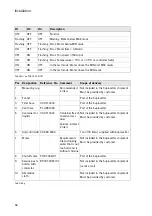
Tab. LEDs
LED
Normal mode
Test mode
H1
Error: Water level or water flow rate MAX level OK
H2
Error: Fan
MIN level OK
H3
Error when flashing 1 sec.
-
H4
Unit is heating
-
H5
Unit is cooling
-
H6
Firmware running when flashing
-
H7
Unit switched on remotely
-
H8
24V power
-
Содержание Suprasetter A52
Страница 6: ......
Страница 24: ...Safety 22 Fig 24 Filter replacement Fig 13 4 On the filter unit ...
Страница 26: ...Safety 24 Fig 26 Warning sign copy template ...
Страница 36: ...Installation Preparation 34 Pallet Installation Instructions ...
Страница 60: ...Installation 58 Fig 51 Power cable strain relief Tighten the strain relief for the power cable Fig 51 1 ...
Страница 82: ...Technical Data 80 Resolution 1000 pixels cm 2540 dpi Type Value Comment ...
Страница 84: ......
Страница 85: ......

