background image

68 

Heatilator • ICON DV-IDV Series • 4042-575 Rev G • 09/07

F. Contact Information

Hearth & Home Technologies Inc.

1915 W. Saunders Street

Mt. Pleasant, Iowa 52641

www.heatilator.com

- NOTES -

DO NOT DISCARD THIS MANUAL

CAUTION

• Important 

operating 

a n d   m a i n t e n a n c e 
instructions included.

• 

Leave this manual with 
party responsible for 
use and operation.

• 

Read, understand 
and follow these 
instructions for safe 
i n s t a l l a t i o n   a n d 
operation.

DO

NOT

DISCARD

This product may be covered by one or more of the following patents: (United States) 4593510, 4686807, 4766876, 
4793322, 4811534, 5000162, 5016609, 5076254, 5113843, 5191877, 5218953, 5263471, 5328356, 5341794, 5347983, 
5429495, 5452708, 5542407, 5601073, 5613487, 5647340, 5688568, 5762062, 5775408, 5890485, 5931661, 5941237, 
5947112, 5996575, 6006743, 6019099, 6048195, 6053165, 6145502, 6170481, 6237588, 6296474, 6374822, 6413079, 
6439226, 6484712, 6543698, 6550687, 6601579, 6672860, 6688302B2, 6715724B2, 6729551, 6736133, 6748940, 
6748942, 6769426, 6774802, 6796302, 6840261, 6848441, 6863064, 6866205, 6869278, 6875012, 6880275, 6908039, 
6919884, D320652, D445174, D462436; (Canada) 1297749, 2195264, 2225408, 2313972; (Australia) 780250, 780403, 
1418504 or other U.S. and foreign patents pending.

Please contact your Heatilator dealer with any questions or concerns. 

For the number of your nearest Heatilator dealer, please visit www.heatilator.com.

Содержание Gas Fireplace IDV4833IH

Страница 1: ...ome and must be installed in accordance with the manufacturer s instructions and the manufactured home construction and safety standard Title 24 CFR Part 3280 or Standard for Installation in Mobile Ho...

Страница 2: ...er s manual for future reference Congratulations on selecting a Heatilator gas appliance an elegant and clean alternative to wood burning appliances The Heatilator gas appliance you have selected is d...

Страница 3: ...s 27 C Install the Heat Shield and Horizontal Termination Cap 28 D Install Roof Flashing and Vertical Termination Cap 30 E Assemble and Install Storm Collar 31 9 Gas Information 32 A Fuel Conversion 3...

Страница 4: ...nts which refers to 15 U S Code USC 2063 stating Such certificate shall accompany the product or shall otherwise be furnished to any distributor or retailer to whom the product is delivered Some local...

Страница 5: ...ilding at a minimum height of eight 8 feet above grade directly in line with the exhaust vent terminal for the horizontally vented gas fueled heating appliance or equipment The sign shall read in prin...

Страница 6: ...ne Safety glasses Level Manometer Voltmeter Tape measure Non corrosive leak check solution 1 2 3 4 in length 6 or 8 self drilling screws Keep appliance dry Mold or rust may cause odors Water may damag...

Страница 7: ...ons diagrams are not drawn to scale Actual installation may vary due to individual design preference Fire Risk Provide adequate clearance Around air openings For service access Locate appliance away f...

Страница 8: ...iling base plate and cantilever floor of the chase should be insulated Vapor and air infiltration barriers should be installed in the chase as per regional codes for the rest of the home Additionally...

Страница 9: ...d surfaces extending full width and depth of appliance Do NOT install appliance directly on carpeting vinyl tile or any combustible material other than wood WARNING Model A Rough Opening Width B Rough...

Страница 10: ...1 4 22 22 3 4 30 in minimum to ceiling 1 2 10 10 3 4 Figure 3 3 Clearances to Mantels or Other Combustibles Above Appliance 1 in 25 mm min to perpendicular wall A 7 75 in 159 mm min from fireplace op...

Страница 11: ...insulation or other materials away from vent pipe may cause fire Measure horizontal clearances from this surface Measure vertical clearances from this surface Figure 4 1 Clearances from Cap Surfaces s...

Страница 12: ...now regions Storm Collar Roof Flashing Figure 4 2 Minimum Height from Roof to Lowest Discharge Open ing A Gas Termination Wood or Fuel Oil Termination B 6 in 152 mm min 20 in 508 mm min Direct Vent Ga...

Страница 13: ...y open on a minimum of 2 sides beneath the floor N Vertical clearance between two horizontal termination caps 12 in 30 cm minimum O Horizontal clearance between two horizontal termination caps 12 in 3...

Страница 14: ...A length of straight pipe is allowed between two 45 elbows see Figure 5 1 ALL vent configuration specifications MUST be followed This product is tested and listed to these specifications Appliance per...

Страница 15: ...ly A maximum of three 90 elbows or six 45 elbows may be used in any vent configuration Some elbows may be installed horizontally See Figure 5 6 Elbows may be placed back to back anywhere in the system...

Страница 16: ...25 ft max 7 62 m Figure 5 4 Minimum Installation Requirements for Two 45 Elbows Top Vent Horizontal Ter mination Top Vent Horizontal Termination Three Vertical Elbows See Figure 5 6 for information ab...

Страница 17: ...tally Installed Vertically H2 Figure 5 6 Two or Three Elbows some Horizontal Note Subtract 3 ft 914 mm from the total horizontal measurement for each 90 elbow installed horizontally Subtract 1 1 2 ft...

Страница 18: ...n No Elbows 12 ft 3 66 m min 60 ft 18 29 m max Maximum horizontal run is 100 of vertical but cannot exceed 26 ft 7 92 m Figure 5 10 Vertical Termination Two Elbows Figure 5 8 12 ft to 30 ft Vertical R...

Страница 19: ...m horizontal run is 100 of vertical but cannot exceed 26 ft 7 92 m Figure 5 11 Vertical Termination Three Elbows some horizontal Note Subtract 3 ft 914 mm from the total horizontal measurement for eac...

Страница 20: ...p insulation or other materials away from vent pipe may cause fire WARNING Figure 6 1 Minimum Top Vented DV Pipe Clearances 3 in 76 mm top clearance 1 in 25 mm clearance bottom sides 1 in 25 mm cleara...

Страница 21: ...ceiling firestop may be installed above or below the ceiling Refer to Figure 6 5 Secure with three fasteners on each side Do not pack insulation around the vent Insulation must be kept away from the...

Страница 22: ...rance Vaulted Ceiling Installation The attic insulation shield has been laser etched with cut lines and ceiling pitches to make field trimming easier Remove one shield from box Note Cut previously ins...

Страница 23: ...liance as necessary It is acceptable to use wood shims Bend out nailing tabs on each side Keep nailing tabs flush with the framing Secure the appliance to the framing by using nails or screws through...

Страница 24: ...ding two stories or High rise Applications For installation into a commercial multi family multi level exceeding two stories or high rise application All outer pipe joints must be sealed with high tem...

Страница 25: ...2 Once both inner and outer flues are started press section A onto section B firmly until all lances have snapped into place Check to make sure they have snapped together see Figure 8 3 and the seams...

Страница 26: ...e attached by fitting another pipe section to it and snapping it together as normal Assemble Slip Sections The outer flue of the slip section should slide over the outer flue of the pipe section and i...

Страница 27: ...ipe rotate either section see Figure 8 10 so that the seams on both pipe sections are aligned see Figure 8 11 They can then be carefully pulled apart Figure 8 8 Securing Vertical Pipe Sections Figure...

Страница 28: ...the termination cap There are two sections of the standard heat shield One sec tion is factory attached to the wall shield firestop The other section is factory attached to the cap See Figure 3 1 If...

Страница 29: ...and CAN CGA B149 installation codes INTERIOR Heat Shield or Extended Heat Shield Wall Shield Firestop Heat Shield 1 1 2 in 38 mm min overlap EXTERIOR SHEATHING Vent depth from back of appliance to out...

Страница 30: ...2 to 12 12 4 0 Over 6 12 to 7 12 1 25 Over 12 12 to 14 12 5 0 Over 7 12 to 8 12 1 5 Over 14 12 to 16 12 6 0 Over 8 12 to 9 12 2 0 Over 16 12 to 18 12 7 0 Over 9 12 to 10 12 2 5 Over 18 12 to 20 12 7 5...

Страница 31: ...he brackets and tighten the nut to complete the storm collar assembly Make sure the collar is tight against the pipe section See Figure 8 17 Slide the assembled storm collar down the pipe section unti...

Страница 32: ...13 mm T handle manual shut off valve and flexible gas connector are connected to the 1 2 in 13 mm control valve inlet If substituting for these components please consult local codes for compliance Pr...

Страница 33: ...allation is complete all connections must be tightened and checked for leaks with a commercially available non corrosive leak check solution Be sure to rinse off all leak check solution following test...

Страница 34: ...Incorrect wiring will override IPI safety lockout and may cause explosion WARNING C Intellifire Ignition System Wiring This appliance requires a 110 VAC supply to the appliance junction box for operat...

Страница 35: ...Verify proper operation after servicing CAUTION Shock Risk Replace damaged wire with type 105 C rated wire Wire must have high temperature insulation WARNING Ignitor Flame Sensor Pilot Assembly GRN OR...

Страница 36: ...ppliance with two screws Figure 10 2 Remove Two Screws From Bracket If the junction box is being wired from the INSIDE of the ap pliance Remove one screw that attaches access panel to column See Figur...

Страница 37: ...Noncombustible Facing Diagram 11 11 Finishing Fire Risk Finish all edges and fronts to clearances and specifications listed in manual WARNING Appliance front may be covered with non combustible mater...

Страница 38: ...use of a decorative screen front not provided with the appliance F Refractory All refractory internal to the firebox comes pre installed See Section 12 I for installation of bottom front and side refr...

Страница 39: ...Align opposite end of log with white notched area in top of base log Repeat for each top log See Figures 12 1 through 12 6 Figure 12 1 Placing First Top Log ICON60I Figure 12 2 Placing Second Top Log...

Страница 40: ...s Panel Assembly Removing Replacing Glass Assembly See Figure 12 8 Remove three outer refractory pieces as per instructions in Section I Remove the lower decorative front face by removing the four scr...

Страница 41: ...side of the screen rod into the horseshoe shaped cradle see Figure 12 11 Rotate the right side of the rod up and into the cradle on the right see Figure 12 12 Note Make sure the outside screen eyelet...

Страница 42: ...Install Side Refractories Locate right side refractory panel See Figure 12 17 Install rod in hole in glass frame top See Figure 12 18 Insert Pin Notch Figure 12 18 Insert Pin into Top Frame Insert Pin...

Страница 43: ...iance has an adjustable air shutter which controls the primary air Adjustment of the air shutter may be neces sary to obtain optimal flame appearance This should be adjusted by a qualified installer a...

Страница 44: ...ith an integral barrier to prevent direct contact with the fixed glass panel Do NOT operate the appliance with the protective barrier removed Contact your dealer or Hearth Home Technologies if the bar...

Страница 45: ...the appliance WARNING If you do not follow these instructions exactly a fire or explosion may result causing property damage personal injury or loss of life FOR YOUR SAFETY READ BEFORE LIGHTING 33631D...

Страница 46: ...o NOT store flammable materials in the vicinity of the appliance Do NOT use gasoline lantern fuel kerosene charcoal lighter fluid or similar liquids in this appliance Combustible materials may ignite...

Страница 47: ...ocker switch or wall switch to OFF position Remove ignitor wire I from module Place ON OFF rocker switch or wall switch in ON position Hold ground wire about 3 16 in away from I terminal on module If...

Страница 48: ...ire harness is firmly connected to module D Damaged pilot assembly or dirty sensor rod Verify that ceramic insulator around the sensor rod is not cracked damaged or loose Verify connection from sensor...

Страница 49: ...grilles control compartment Burner burner ports Risk of Fire Delayed ignition or explosion Exposure to combustion fumes Odors WARNING Handle glass assembly with care Note Clean glass after initial 3 4...

Страница 50: ...foration Sand and repaint as necessary 2 Replace appliance if firebox has been perforated Burner ignition and operation 1 Verify burner is properly secured and aligned with pilot or ignitor 2 Clean of...

Страница 51: ...er to Sec tion 3 B D E 1 in 25 mm 29 1 2 in 749 mm C A Gas Line Electric Line 9 7 8 in 251 mm 13 3 8 in 340 mm 2 in 51 mm 2 1 4 in 57 mm F 21 1 2 in 546 mm Figure 16 1 Appliance Dimensions 16 16 Refer...

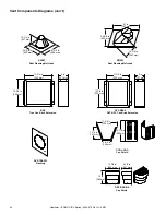
Страница 52: ...Termination Cap High Wind Includes storm collar and fastener pack PVK 80 Power Vent Kit DVP TV Vertical Termination Cap Includes storm collar fastener pack DVP TB1 Basement window well termination ca...

Страница 53: ...12MI 3 to 12 in 76 to 305 mm DVP24MI 3 to 24 in 76 to 610 mm 10 1 2 in 267 mm 10 7 8 in 276 mm DVP45 45 Elbow 45 4 7 8 in 124 mm Assembled Height 24 in 610 mm Diameter 10 in 254 mm DVP AS2 10 in 254 m...

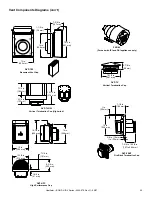
Страница 54: ...625 mm 13 1 4 in 367 mm RF12M Roof Flashing Multi pak BEK Trap Cap Brick Extension 13 3 4 in 349 mm 5 in 127 mm 13 3 4 in 349 mm DVP BEK2 DVP HPC Cap Brick Extension 13 7 8 in 352 mm 5 in 127 mm 11 7...

Страница 55: ...use with IPI and DSI appliances only 1 in 25 mm 14 in 356 mm 3 8 in 10 mm 1 in 25 mm 7 1 4 in 184 mm 7 3 4 to 10 3 8 in 197 to 264 mm DVP FBHT Fire Brick Termination Cap 7 1 4 in 184 mm 5 1 4 in 133 m...

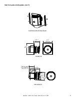
Страница 56: ...mum Term Cap Effective Length Effective Length TRAP1 4 1 8 in 5 5 8 in 105 mm 143 mm TRAP2 6 3 4 in 10 5 8 in 171 mm 270 mm Note Heat shields MUST overlap by a minimum of 1 1 2 in 38 mm The heat shiel...

Страница 57: ...Components Diagrams con t 13 in 330 mm 15 in 381 mm 8 1 8 in 206 mm DVP HRC SS 10 7 8 in 276 mm 10 1 2 in 267 mm 3 87 Effective Length 5 3 4 to 8 3 8 in 146 to 213 mm 5 1 2 in 140 mm 8 3 8 in 213 mm...

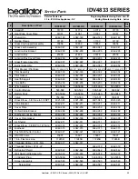
Страница 58: ...ervice Parts List IDV4833 SERIES Service Parts Exploded Parts Diagram Beginning Manufacturing Date Jan 07 33 in ICON Gas Appliance DV Ending Manufacturing Date Active 4 3 2 1 6 7 9 8 12 13 14 11 10 5...

Страница 59: ...affle 4045 203 4045 203 4045 203 4045 203 1 16 Wire Assembly 593 590A 593 590A 593 590A 593 590A 1 17 Control Module 593 592 593 592 593 592 593 592 1 18 Battery Pack 593 594A 593 594A 593 594A 593 59...

Страница 60: ...42 575 Rev G 09 07 Service Parts IDV4833 SERIES Exploded Parts Diagram Beginning Manufacturing Date Jan 07 33 in ICON Gas Appliance DV Ending Manufacturing Date Active 2 1 3 4 5 6 7 8 Front Refractory...

Страница 61: ...042 454 4042 455 4042 454 4042 455 1 9 Front Hearth Refr 4042 466 4042 466 4042 466 4042 466 1 10 Left Front Refractory 4042 459 4042 463 4042 459 4042 463 1 11 Right Front Refractory 4042 458 4042 46...

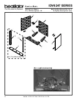
Страница 62: ...G 09 07 IDV6247 SERIES Service Parts Exploded Parts Diagram Beginning Manufacturing Date Jan 07 47 in ICON Gas Appliance DV Ending Manufacturing Date Active 4 3 2 1 6 7 9 8 12 13 14 11 10 5 15 33 16 1...

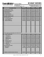
Страница 63: ...ffle 4045 203 4045 203 4045 203 4045 203 1 16 Wire Assembly 593 590A 593 590A 593 590A 593 590A 1 17 Control Module 593 592 593 592 593 592 593 592 1 18 Battery Pack 593 594A 593 594A 593 594A 593 594...

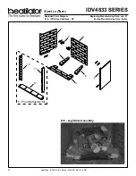
Страница 64: ...42 575 Rev G 09 07 IDV6247 SERIES Service Parts Exploded Parts Diagram Beginning Manufacturing Date Jan 07 47 in ICON Gas Appliance DV Ending Manufacturing Date Active 12 Log Grate Assembly 2 1 3 4 5...

Страница 65: ...ractory 4042 467 4042 467 4042 467 4042 467 1 10 Left Front Refractory 4042 461 4042 465 4042 461 4042 465 1 11 Right Front Refractory 4042 460 4042 464 4042 460 4042 464 1 For Complete Log Set Assemb...

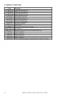
Страница 66: ...orative front DF SAL47 BK Salem black decorative front DF SAL47 BZ Salem bronze decorative front WSK MLT HTL Multi function wall switch RC BATT HTL Remove control RC SMART HTL Remote control requires...

Страница 67: ...ons inadequate ventilation or drafting caused by tight sealing construction of the structure air handling devices such as exhaust fans or forced air furnaces or other causes 5 use of fuels other than...

Страница 68: ...34 5000162 5016609 5076254 5113843 5191877 5218953 5263471 5328356 5341794 5347983 5429495 5452708 5542407 5601073 5613487 5647340 5688568 5762062 5775408 5890485 5931661 5941237 5947112 5996575 60067...

Отзывы: