background image

Содержание Heathkit HD-1410

Страница 1: ...HEATHKIT MANUAL for the ELECTRONIC KEYER Model HD 1410 595 1692 06 COMPANY BENTON HARBOR MICHIGAN...

Страница 2: ...cts SUCH REPAIR AMU REPLACEMENT SMAll BE IM SOLt REMEDY OF THE CUSTOMER AN J IHE RE SMALL BE NO LIABILITY UN IHt PARI OF M6ATH FUR Afjy SPECIAL INDIRIl T INCIDENTAL OR CONStOUtN PAL DAMAGES INC LUDING...

Страница 3: ...Panel Assembly 34 Rear Panel Assembly 33 Final Wiring 43 Knob Installation 4S Tests and Adjusbnents 46 Final Assembly 49 Installation 52 Operation 54 In Case of Difficulty 55 Troubleshooting se Specif...

Страница 4: ...ck on the rear panel that silences the speaker Recaivsr audio fed to the headphones by a separate rear panel jack Solid state output eliminates the bounce and sticking problems associated with relays...

Страница 5: ...tp you aasily Idwitify the same part h Mefien of vih Manual ThMa numban wrtll spaar QTY DtSCRIPTION PART CIRCUIT 1 0 pgrn nant No NOTE The resistors may be packed in more than one envelope Open all th...

Страница 6: ...k 1 2 12 n 1 0r n rad all 2200 m rad Tad 1 4 12 R1 R2 R16 f 6 4700 a y Gw Vl6l 1 8 12 R14 R15 R22 red R23 R24 R26 1 red 1 26 12 m K 1 8200 n Igrav redTBd t 12 R21 1 10 kn brown tvck R9 1 R8 n4 orange...

Страница 7: ...57 C103 r t fiF disc 21 9 ce eg r 2 2 AtF disc 21 99 07 0101 2 2 electrolytic 25 123 C5 06 1 2 2 fxF electrolytic 25 924 C3 2 22 fiF electrolytic 25 233 CI C2 1 100Q eiijctrptytie 25 164 Gil 1 1N709Az...

Страница 8: ...ar than the one llited 1 D40C1 transistor 417 272 Q8 1 X29A829 transistor 417 201 Q2 I 2 MPSA42tramiitor 41 tt l d I 3 vMPSA20tran liior 417 801 Q1 03 04 r 1 MPS D51 tramlttor 417 836 05 INTEGRATED CI...

Страница 9: ...1 Neon lamp 1 1 16 anipere slow blow fuse f 1 Speaker WIRE SLEEVING I 12 Bare wire For soldering iron tip r 36 Black wire f 36 Red wire J 36 Large brown wire f 96 Small brown wire 1 Small black sleev...

Страница 10: ...ware against the Parti 2 The hardware is mf mMu You ean WMpy t Mt y ifacing it on its drawing 2 Hardware 1 1 2 2 56 X B 16 screw 260422 I 2 2 56 nut 262 6t 4 Hardware 10 4 40 X 1 4 screw 2S0 S2 9 4 40...

Страница 11: ...252 23 i 1 6 32 praw ln nut 262 109 2 8 flbw flat wnher 263 1 4 6 shoulder washer 253 2 8 6 metal flat washer 253 60 22 6 lockwasher 254 1 1 6 external lockwasher 254 6 lfie old r lug 2S9 1 Other 2 5...

Страница 12: ...16 spacer 255 74 4 Rivet 256 15 1 Wire spring 258 179 CONNECTORS t 1 Male connector housing 432 148 f 1 Female connector housing 432 149 2 Male terminal pin 432 854 J I 2 Female terminal pin 432 8S5 I...

Страница 13: ...ESCRIPTION Connectors cont d 1 Phone jadt phone plug 3 PH pnaQ 436 21 438 3 43846 CIRCUIT Componant No METAL PARTS 2 Cabinet shell 90 1133 2 1 Right side panel 200 1212 1 Leftsidepanel 200 1211 r Page...

Страница 14: ......

Страница 15: ...st bssG 75 17 i 4 Cabinet nut 75 61 f T 1 Small insulator paper 76 108 1 3 4 X 2 1 Large insulator papw 7Bn10S W V 1 w 3 3 8 X 5 3 8 1 Circuit board 85 1524 2 U 4 Plastic foot 261 34 1 Cam lever 26e M...

Страница 16: ...cement label 390 1255 NOTE Be sure vou refer to the numbers on the blue and white label in any communications you may have about this kit with Heath Company You may w nt tojm hs iir gti e 1 Blue and w...

Страница 17: ...TE When you solder integrated circuit sockets you will need a small wattage small tip sotdertng iron If one of these is not available piui t i il is follows Be sure your soldering iron is cool Then wr...

Страница 18: ...ds to the foil and cut off the excess lead lengths FOR GOOD SOLDER CONNECTIONS YOU MUST KEEP THE SOLDERING IRON TIP CLEAN WIPE IT OFTEN WITH A DAMP i SL SPONQE OR CLOTHT ti v CONTI NU E NOTE Use 1 4 w...

Страница 19: ...older the leads to the foil and cul off the excess lead lengths 1 Ml 1 bare wire WCTOfilAt 1 2 CONTINUE 1 1 4 bare wire 3 4 bare wire r bare wfre 3 4 bare wire 1 2 1 4 bare wire Be sure this wire is p...

Страница 20: ...own btick nd 1 R28 220 brown n 1 g w t tred red 1 R12 270 Ii Ired uiolet brown Solflpc thi 1 1 rl f M li Ltds to ihi toil dPid cui A r id Ir I i tl CONTINUE PICTORIAt 1 3 R9 Use 5600 S gri i n blue rc...

Страница 21: ...t the traniistor leads into their corresponding E B and C holes in the cirtiuii board Solder each iramlRor you insull i and cut oft the axceis lead langthi I Q7 MPSA42 traniisior J17 29rtl I 06 MPSA42...

Страница 22: ...A 120 VAC Wiring 3 4 bare wire 3 4 bare wire SiHdei Hie mnm lo ihe foil and cut off the excess wire lengths OR 240 VAC Wiring 3 4 bare wire Solder ttie wire to the foil and cut off the excess wire Iwr...

Страница 23: ...cesi lead lengths CONTINUE 3 7T R17 Install the 750 control 1 10 934 as follows First insert the control lugs then insert the mounting lugs through the circuit board Seat the control flfmly against th...

Страница 24: ...r the ptnt to tht foil o o o CONTINUE I 1 IC6 7403 IC 443 461 Refer to Detail 1 7A Than poikion the 1 end of this Integrated circuit toward the Index mark on the circuit board Then oarefully Initall t...

Страница 25: ...c C3 2 2 fiF electrolytic C11 1000 juF electrolytic Solder the leads to the foil and cut off the excess lead lengths CENTERS LEAD 0 O PICTORIAL 1 8 CONTIN UEO NOTE To install the transistor in the nex...

Страница 26: ...he Indlciitd length nd remove 1 4 of nsulalion from each end Solder each wire a it is iniialled The fret end o1 each wire will be connscied later 3 1 2 wiranJ V3 Witt U H 3 1 2 wlnrnQ 1 5 3M wlriMF 2...

Страница 27: ...ections Solder bridges between foil patterns Protruding leads which could touch tooether Integrated circuits for the proper type and installation Transistors for prcqwr type and installation Electroly...

Страница 28: ...x 5 16 screw two shoulder washers a 4 solder lug ar d a 440 nut Be sure the rivet is centered in the hole and does not touch the bracket Similarly mount a contact plate assembly at S103B NOTE When ha...

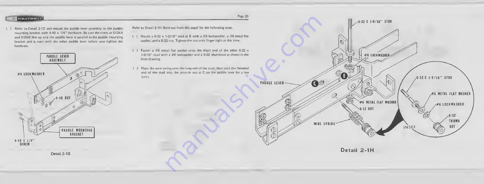
Страница 29: ...1 4 hardware r Mount sprir to the paddle lever 4 40 x 1 4 hardvrare FUT SPMKfi 4 40X1 4 SCREW Detail 2 1C Detail 2 1D ti Refer to Detail 2 D and mount the paddle levtii assembly to the paddle mountin...

Страница 30: ...se orcither hard surface as shown 2 Place ihii piiisvni nut idged side down ab0W VDA to HlSB VKiththe indicated hole in the paddle lever 3 Tap the press in nut firmly v rith a hammer until the press i...

Страница 31: ...fold out from this pige for the following sMpi I Mount a 6 32 x 1 9 1 6 stud at E with a 6 lockwasher a 6 metal flat washer and a 6 2 nut Tighten the nut only finger tight at thii timt Fasten a G meta...

Страница 32: ...r as shown Turn the cam lever counterclockwise until the rivets on either or both sides of the paddle levers touch If the rivets on both sides do not touch at exactly the same time move the 6 32 x 1 9...

Страница 33: ...440 X 5 1 6 hardware t Mount th9 teft side par l to the circuit board at the three locations own with 44S X hntMai V f tf yW wfch to wire the Keyer for right hand operation position the wires corning...

Страница 34: ...hardware panels at F and G with a 6 32 x 3 8 flat head screw a 6 metal fM 4tQ iiEJM ti tr washer a 6 lockwasher and a 6 32 nut at each location u Again refer to Detail 3 18 and loosely mount the paddl...

Страница 35: ...ion The number ftSr the S telts how many wires are at the connection Position eat wfreor component as shown in the Pictorial 2 The following steps are in two specific groups One group is for right han...

Страница 36: ...39 for the following steps Refer to Detail 4 1 A aiKt mount the red lens in hole A In the front panel WtKh push on nut INSISE nSH ON NUT Detail 4 1 0 I 1 B 3 0 I 6 8 7 e i i i i PL1 Refer to Part 2 an...

Страница 37: ...uui i notch in a 1 length ol clear sleeving Position the 33 kiZ resistor and the 1 brown wire through tiie notch in the sleeving and out the opposite ends as shown in DMdM 4 10 filM rillitf It over t...

Страница 38: ...g from circuit txurd h rie D Arough control R101 lug 1 S 2 to Iug2 S l Connect the free end of the wire coming from hole E in the circuit board j toswitchSIOI Iub2 S 1 Connect one end of a 7 1 4 lengt...

Страница 39: ...ore you tighten the hardware NOTE When you are instructed to make a mechanically secure connection as in the next tVvD steps refer to the inset drawing on notorial 4 2 Connect one end of a 6 3 4 large...

Страница 40: ...SlmilarivAdOmaAft liihotto socket at K SlfflHarly mount the remaining phorto socket at L 6 32 X 3 8 SCREW INSIDE OF REAR PANEL mm PAMT 6 LOCKWASN 6 32 NUT CONNECTOIt HOUSING Dftatl 6 1 I Rwter to D i...

Страница 41: ...05MFl400V 1 4kV dl8CcapacltorrromACaock t P lug 2 N8 to solder lug T 8 1 FEMALE TERMINAL PINS UT OFF BANDS 0MI16 1D FEMALE TERMINAL PIN lEND 0V m SOLDER DatafI 5 1 E Rofar to Detail 6 1 D and cut the...

Страница 42: ......

Страница 43: ...oard hole F to Phono socket L lug 1 S 2 Route this wire around the transformer as sbown in the Pictorial Connect the free end of the wire coming from circuit board hole J to phono socket K lug 1 S 21...

Страница 44: ...as shdwiitv l iitfi the he t uri ii jff jiff the transistor as far as possible IW 5 3B Q8 Refer to Detail 5 3C and install the transistor heat sink assembly as shown Match the bevel on the transistor...

Страница 45: ...ASKER fg 6 32 3 8 SCREW Detail 6 1 Page 43 Refer to Detail 6 1 A and mount the fus rOl at S with a 6 32 x 3 8 screw a 6 external lockwasher a 6 lOCkWfidier and a 6 32 nut as diown f Connect the free e...

Страница 46: ...w blow fuse not supplied Detail 6 1C Push one end of the fusu into either fuseholder clamp Slide the prepared 2 1 4 Isngth of sleeving over the free end of the fuse then push this end Refer to Detail...

Страница 47: ...her knob on tha VOLUME OOflVal turt tha knob pointer is toward OFF NOTE You ihouM hava althar a 10 kA or a 6600 SI mistor laft ovar dapanding on which speed rang voti nlaotad Sava tNi rwlMor hi oaa yo...

Страница 48: ...et your ohmmeter on the RX1O0 scale CbnoKt the common lead of yoiir ohmmeter to either sTde psnel NOTEi The resistances In the following steps are the minimum desired If the resistance readings are si...

Страница 49: ...a character This is nomiat If Keyw emits a steady tone tiMich one of the peddles to reset the otreuiov Turn the VOLUME control fully clockwise hkI the SPEED control to 12 o clock Push the right paddl...

Страница 50: ...requency tone Use a small screwdriver and adjust the TONE control through the hol marked Tone on tht foil lidfl of th eiroult board for the desifi r tom PadcUaTraval t Loosen the thumbnut on top of th...

Страница 51: ...two 2 56 X 6 16 screws two 6 flat washers and two 2 56 nuts Use tiie holes that most closely line up with the holat In the lead weight Tighten each screw until iu end Is flush with the nut I Locate th...

Страница 52: ...ath Company about this kii This assures you that you W fii Kve the most complete and up to date information in return Carefully peel away the paper backing from the blue and white labti Than press the...

Страница 53: ......

Страница 54: ...th the point up and push the male pin on the black wire into the upper hole as shown until tite pin locks in place Similarly puili tfta pin oi the red wire Into the lowar holt iMvIng the center hole o...

Страница 55: ...ing the Keyer with a transmitter BASIC CONNECTION WITH EXTERNAL HAND KEY OR KEYING MECHANISM Figure 8 diows how to connect the Keyer for use with an external hand Icey The hand Icey will key the trans...

Страница 56: ...neouslv a itring of alternate dots and dashes will result The first bit is determined by which paddie you depress first The duai memories allow you to insea a doi into a series of dashes Simply close...

Страница 57: ...kit builder 2 AJbout 90 of the khs that are returned to the Heath Company for repair do not function n perly due to poor connections and soldering Thwefore many troubles can be eliminated by reheating...

Страница 58: ...lip for example and short across components or voltage sources it is very likaiy to cause damage to one or more IC s transistors or diodes 3 High voltages are exposed in the Electronic Keyer when the...

Страница 59: ...C5 C6 03 105 or open speaker Will not key transmitter sidetone okay OS 06 or 07 W NdtftMM NOTE This Keyer is designed to be compatible with most ngs that use solid state keying circuits as well as th...

Страница 60: ...voltage open circuit or spikes 300V Max current 200mA Negative line to grourtd Max voltage open circuit or spikes 200V Max Gu nint iOnUk Audio 1 Internal speaker or high impedance at least 500 12 Ifco...

Страница 61: ...olti RaselM r aiidtoi Exttmal key 5 1N4002 silicon 3 GD 510 germanium 2 1N2071 silicon 1 1N70gA zener 1 X29A829 PNP 3 MPS A20 NPN 1 MP PNP 2 1 D40C1 DarHfvtwb 2 7400 Quad 2 inpul positive NAND gate 1...

Страница 62: ...e Heath Company reserves the right to discontinue products and to change specifications at any time without incurring any obligation to incorporate new faatum In products pravtoutly sold CIRCUIT DESCR...

Страница 63: ...gh resistor RS Speed control R101 and resistor R11 When its v tage drops to the base potential of Ql 01 begins to turn on The collector of Q1 and the base of Q2 begin to go less positive and turn on Q...

Страница 64: ...circuitry IC5B IC2D resistor R3 and capacitor CI form the dash reset cIrouK The dot reset circuitry is composed of ICSA IC2C resistor R4 and capacitor C2 operates the same Iambic operation requires t...

Страница 65: ...d Transistor Q4 also turns on thus turning on transistor 05 and keying negative lines to ground through the power supply and resistor R25 Note that no more than approximately 10 mA may be keyed by thi...

Страница 66: ...lHeimnt A Find the circuit component number R16 C3 mc on the X ay View or Chassis Photograph B Locate this same number in the Circuit Component Number Ci Adjacent to the cfrcult component number you w...

Страница 67: ......

Страница 68: ......

Страница 69: ......

Страница 70: ...FIGATION D7 56 58 1N709A ZENER OlODE 6 2V 2SfnA MPOITiWT TIE UNIED ENI OF DIOBES CftK M D2 D3 56 89 GD 510 GERMANIUM DIOOE 25V 100mA BE IMIEB IN A NliBER OF WAYS 04 05 57 27 1N2071 SILICON DIOOE 60aV...

Страница 71: ......

Страница 72: ...ICl IC2 IC4 445 1 44J 5 7400 7473 TOP VI EWj Vcc QUAD 2 INPUT r n 1 T 1 V r TOP VIEW J Q 0 GND K 0 Q jjHiMiJHiHJjHlHi CLOCK ClEMt K VCC CmCR CLEAR J DUAL i K MASTER SLAVE TRUTH TABLE m a r h r i D r...

Страница 73: ...SYWIOl IHPICAtIS A UIKNEO CiaCUIt ROAIO CONNfCtlOX IhAI is SOlOtRED V i lHiS STMBOi IhDICAIIS A PAH HfT MOVHTtO ON THE WCIRCUM lOARB IB IHOICAttS ClOCKWISI ROTAIIOK OF COHtROl SMAFT ll XHIl STMIOl IHB...

Страница 74: ...sitions connections to other units operating procedures voltage readings and any other infor mation you think might be helpful Please do not send parts for testing unless this is specill cally request...

Страница 75: ...HEATH HEATH COMPANY BENTON HARBOR MICHIGAN THE WORLD S FINEST ELECTRONIC EQUIPMENT IN KIT FORM UIHO IN U S A...

Отзывы: