background image

PRO

3

 Side Mount Packaged Refrigeration System Installation and Operations Manual, May 008 


 1

PRO

3

 Side Mount Packaged Refrigeration System

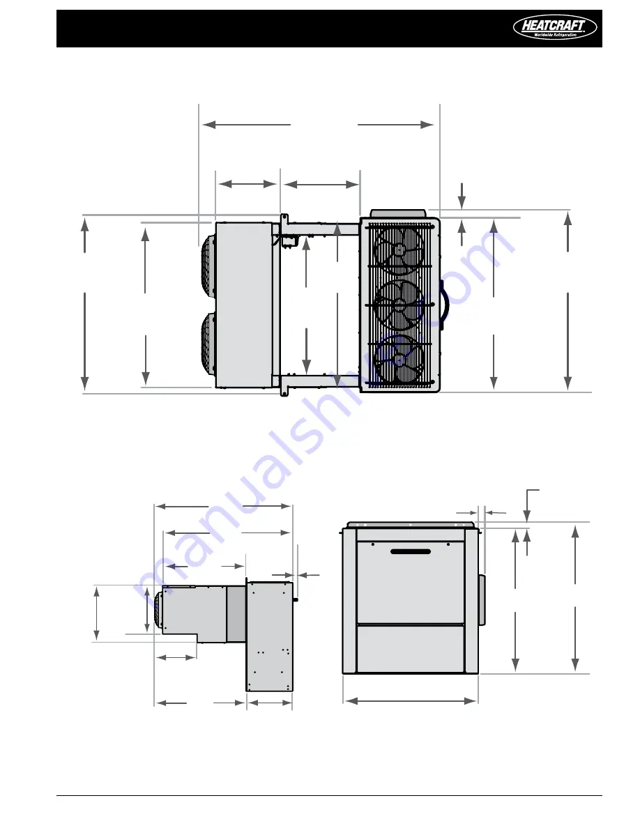
49-1/8"

12-1/4"

29-5/8"

16-5/8"

20-1/4"

1-3/4"

46-1/4"

514 mm

311 mm

422 mm

44 mm

1248 mm

1175 mm

752 mm

32-5/8"

905 mm

17-1/4"

438 mm

37-3/4"

36"

36-1/2"

927 mm

34"

864 mm

959 mm

914 mm

49-1/8" 

1248 mm

16-1/4"

413 mm

13-3/8"

340 mm

29"

737 mm

1-3/4"

45 mm

33-7/8"

860 mm

36"

914 mm

978 mm

1-5/8"

38-1/2"

1019 mm

40-1/8"

41 mm

1-3/4"

44 mm

DIAgRAM 8

 Dimensions | Large Cabinet: 2-fan | Top view

DIAgRAM 9

 Dimensions | Large Cabinet: 1-fan | Side view

DIAgRAM 10

 Dimensions | Large Cabinet: 1-fan | Back view

Содержание PRO3 Side Mount

Страница 1: ...PRO3 Side Mount Packaged Refrigeration System Bulletin H IM PSM May 2008 Part Number 25008001 Installation and Operations Manual ...

Страница 2: ...ow to change the set point How to start a manual defrost How to change a parameter value The Hidden Menu 9 How to Enter the Hidden Parameters How to Move a Parameter from the Hidden Menu How to Lock the Keyboard The Continuous Cycle The On Off Function Parameters 10 11 Regulation Display Defrost Fans XR60CX ONLY Alarms How to use the Hot Key 11 How to program a Hot Key from the Instrument Alarm Si...

Страница 3: ... prevent damage 8 Avoid removing the shipping base until the unit has been moved to the final destination Installation Requirements Recommended Unit Placement 1 Ensure that the structural integrity of the box can withstand the weight of the side mounted equipment 2 The air pattern must cover the entire room 3 Location of aisles racks etc must be known 4 For space requirements see FIGURES 1 and 2 A...

Страница 4: ...where it is feasible In order to install a unit using this method you will need to provide cutout slots for the arms The unit should be placed on the wall prior to setting and securing the roof of the box Pleaseusethefollowingguidelineswhencompletingtheinstallation in this manner 1 You will need to provide finished slots with the appropriate dimensions in the box wall See FIGURES 5 and 6 2 The slo...

Страница 5: ...letingtheinstallation in this manner 1 Provide a finished opening with the appropriate dimensions from Figure 8 or 9 2 The cut out section should not be placed in a location where it would degrade the structural integrity of the box should not interfere with cam locks 3 The unit will need to be lifted to the appropriate height and inserted into the open slot The bottom of the unit should be tempor...

Страница 6: ...nside of the box should be reinforced with wood or metal for proper when mounting of the unit to the box with through bolts 2 Install and secure the roof of the box Inside the box provisions have been made to secure the evaporator section to the roof panel with through bolts 3 The area between the evaporator section and the roof panel should be caulked to meet NSF codes In addition the openings wh...

Страница 7: ...e pages 7 16 Cooler with Electric Defrost and Freezer Sequence of Operation Power is provided to the temperature control and compressor contactor The drain line heater as well as the crankcase heaters will also have continuous power supplied to them The temperature controller energizes the compressor contactor starting the compressor and condenser fan s The evaporator fans will be energized by the...

Страница 8: ...ges in this level be made only by a qualified technician Front Panel Commands Button Command To display target set point in programming mode it selects a parameter or confirm an operation DEF To start a manual defrost UP To see the max stored temperature in programming mode it browses the parameter codes or increases the displayed value DOWN To see the min stored temperature in programming mode it...

Страница 9: ...Hidden Menu The hidden menu Includes all the parameters of the instrument How to enter the hidden parameters 1 Enter the Programming mode by pressing the Set DOWN keys for 3 seconds the C or F LED starts blinking 2 Release the keys then push again the Set DOWN keys for more than 7 seconds The Pr2 label will be displayed immediately followed from the HY parameter NOW YOU ARE IN THE HIDDEN MENU 3 Se...

Страница 10: ...be 0 255 min time during which the compressor is OFF in case of faulty thermostat probe With COF 0 compressor is always active Pr2 0 255 minutes 6 6 6 Display CF Temperature measurement unit C Celsius F Fahrenheit WARNING When the measurement unit is changed the SET point and the values of the parameters Hy LS US Ot ALU and ALL have to be checked and modified if necessary Pr2 C Celsius F Fahrenhei...

Страница 11: ... C SET 230 F when this temperature is reached the alarm is enabled after the ALd delay time Pr2 ALL 302 38 50 50 ALL Minimum temperature alarm 50 0 SET C 58 230 F when this temperature is reached the alarm is enabled after the ALd delay time Pr2 58 ALu 25 15 30 How to Use the Hot Key How to program a hot key from the instrument upload 1 Program one controller with the front keypad 2 When the contr...

Страница 12: ...mingmode noneparameterispresentinPr1 On the display the selected probe is not enabled noA None alarm is recorded Technical Data Characteristic Description Housing self extinguishing ABS Case XR40CX XR60CX frontal 32x74 mm depth 60mm Mounting XR40CX XR60CX panel mounting in a 71x29mm panel cut out Protection IP20 Frontal protection XR40CX XR60CX IP65 Connections Screw terminal block 2 5 mm2 wiring ...

Страница 13: ...ollowing items at least once every six months 1 Check and tighten ALL electrical connections 2 Check all wiring and insulators 3 Check contactors for proper operation and for worn contact points 4 Check all fan motors Tighten motor mount bolts nuts and tighten fan set screws 5 Clean the condenser coil surface 6 Check the operation of the control system Make certain all safety controls are operatin...

Страница 14: ...ORMATION WHICH IS THE PROPERTY OF HEATCRAFT REFRIGERATION PRODUCTS AND IS SUPPLIED ONLY ON A PROPRIETY BASIS NO TRANSMITTAL SHALL BE MADE TO ANY PERSON FIRM OR CORPORATION WITHOUT PRIOR WRITTEN APPROVAL TOLERANCES UNLESS OTHERWISE SPECIFIED SHEET METAL CUT SIZE 03 HOLE DIAMETER 005 ENDPLATE TUBE HOLE 001 C L OF HOLES 02 ANGLES 2 FORMED DIMENSIONS 0 TO 36 03 36 TO 120 06 OVER 120 13 DRAWN DATE DATE...

Страница 15: ...NDENSER FAN MOTOR CC COMPRESSOR CONTACTOR EFM EVAPORATOR FAN MOTOR LEGEND HL HEATER LIMIT THERMOSTAT DH DEFROST HEATER GND GROUND RC RUN CAPACITOR SR START RELAY USE COPPER CONDUCTORS ONLY FACTORY WIRING FIELD WIRING SC START CAPACITOR HPS HIGH PRESSURE SWITCH PRIMARY SINGLE PHASE PROTECTION PROVIDED PRIMARY SINGLE PHASE PROTECTION PROVIDED CCH CRANKCASE HEATER PFC PRESSURE FAN CYCLE SWITCH DLT DR...

Страница 16: ...HEATER GND GROUND RC RUN CAPACITOR SR START RELAY USE COPPER CONDUCTORS ONLY FACTORY WIRING FIELD WIRING SC START CAPACITOR HPS HIGH PRESSURE SWITCH PRIMARY SINGLE PHASE PROTECTION PROVIDED PRIMARY SINGLE PHASE PROTECTION PROVIDED CCH CRANKCASE HEATER PFC PRESSURE FAN CYCLE SWITCH DLT DRAIN LINE THERMOSTAT DLH DRAIN LINE HEATER TFC TEMPERATURE FAN CYCLE SWITCH WN WIRE NUT SW SWITCH EFM TOP VIEW OF...

Страница 17: ...R CONTACTOR EFM EVAPORATOR FAN MOTOR LEGEND HL HEATER LIMIT THERMOSTAT DH DEFROST HEATER GND GROUND RC RUN CAPACITOR SR START RELAY USE COPPER CONDUCTORS ONLY FACTORY WIRING FIELD WIRING SC START CAPACITOR HPS HIGH PRESSURE SWITCH PRIMARY SINGLE PHASE PROTECTION PROVIDED CCH CRANKCASE HEATER PFC PRESSURE FAN CYCLE SWITCH DLT DRAIN LINE THERMOSTAT DLH DRAIN LINE HEATER TFC TEMPERATURE FAN CYCLE SWI...

Страница 18: ...MOSTAT DH DEFROST HEATER GND GROUND RC RUN CAPACITOR SR START RELAY USE COPPER CONDUCTORS ONLY FACTORY WIRING FIELD WIRING SC START CAPACITOR HPS HIGH PRESSURE SWITCH PRIMARY SINGLE PHASE PROTECTION PROVIDED PRIMARY SINGLE PHASE PROTECTION PROVIDED CCH CRANKCASE HEATER PFC PRESSURE FAN CYCLE SWITCH DLT DRAIN LINE THERMOSTAT DLH DRAIN LINE HEATER TFC TEMPERATURE FAN CYCLE SWITCH WN WIRE NUT SW SWIT...

Страница 19: ...t Refrigerant Charge oz Approximate Net Weight lbs kg Coolers PST070H6B R 404A 36 260 118 PST090H6B R 404A 36 265 120 PST131H6B R 404A 40 320 145 PST147H6B R 404A 40 325 148 Coolers with electric defrost PST066M6B R 404A 36 260 118 PST086M6B R 404A 36 265 120 PST124M6B R 404A 40 320 145 PST141M6B R 404A 40 325 148 Freezers PST034L6B R 404A 36 260 118 PST051L6B R 404A 36 265 120 PST057L6B R 404A 40...

Страница 20: ... 775 mm 27 7 8 708 mm 49 1 8 12 1 4 29 5 8 16 5 8 20 1 4 1 3 4 46 1 4 514 mm 311 mm 422 mm 44 mm 1248 mm 1175 mm 752 mm 32 5 8 905 mm 17 1 4 438 mm 30 762 mm 34 864 mm 35 5 8 905 mm 1 3 4 44 mm 1 5 8 41 mm Diagram 5 Dimensions Small Cabinet 1 fan Top View Diagram 6 Dimensions Small Cabinet 1 fan SideView Diagram 7 Dimensions Small Cabinet 1 fan BackView ...

Страница 21: ...22 mm 44 mm 1248 mm 1175 mm 752 mm 32 5 8 905 mm 17 1 4 438 mm 37 3 4 36 36 1 2 927 mm 34 864 mm 959 mm 914 mm 49 1 8 1248 mm 16 1 4 413 mm 13 3 8 340 mm 29 737 mm 1 3 4 45 mm 33 7 8 860 mm 36 914 mm 978 mm 1 5 8 38 1 2 1019 mm 40 1 8 41 mm 1 3 4 44 mm Diagram 8 Dimensions Large Cabinet 2 fan Top View Diagram 9 Dimensions Large Cabinet 1 fan SideView Diagram 10 Dimensions Large Cabinet 1 fan BackV...

Страница 22: ...1 1 1 1 1 1 1 1 1 1 1 1 Drain line heater thermostat 28917401 1 1 1 1 1 1 1 1 1 1 1 1 H for PSC E for EC motor on evaporator section only Replacement Parts by When contacting the factory for service or replacement parts refer to the model number and serial number of the unit as stamped on the serial plate attached to the unit If replacement parts are required mention the date of installation of un...

Страница 23: ...LLCmakesnowarrantyexpressedor implied of fitness for any particular purpose or of any other nature whatsoever with respect to products manufactured or sold by HeatcraftRefrigerationProductsLLChereunder exceptasspecifically set forth above and on the face hereof It is expressly understood and agreedthatHeatcraftRefrigerationProductsLLCshallnotbeliableto buyer oranycustomerofBuyer fordirectorindirec...

Страница 24: ...ges in specifications without notice Heatcraft Refrigeration Products LLC 2175 West Park Place Blvd Stone Mountain GA 30087 P 800 321 1881 F 770 465 5990 www heatcraftrpd com CLIMATE CONTROL Commercial Refrigeration Parts The name behind the brands you trust H IM PSM 0508 Version 000 ...

Отзывы: