heatco HH SERIES Скачать руководство пользователя страница 15


15 

Annual Furnace Inspection 


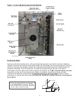
1.  The duct furnace should be inspected annually by a qualified service agency. The condition of the burners, 

heat exchanger, draft inducer, vent system, operating controls and wiring should be determined. Check for 

obvious signs of deterioration, accumulation of dirt and debris and any heat or water related damage. Any 

damaged or deteriorated parts should be replaced before the unit is put back into service. 

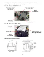
2.  Clean burners, heat exchanger, induced draft fan and vent ducts as outlined on Page 13. 

3.  Check Heat Exchanger for cracks. If any are present, replace heat exchanger before putting unit back into 

service. 

4.  Check the attachment point of the duct furnace to the cabinet to verify that they are airtight. 

5.  Check the automatic gas valve to ensure that the gas valve seat is not leaking 

6.  Check wiring connections to be sure they are secure and inspect wiring for any deterioration. 

7.  Label all wires prior to disconnection when servicing unit. Wiring errors can cause improper or dangerous 

operation. Verify proper operation after servicing. 


Duct Furnace Operation Check 


1.  Prior to heating season, perform annual inspection and verify proper operation. 


2.  Turn on power to the unit and set thermostat or heat controller to call for heat, allowing duct furnace to 

operate. 


3.  Check for proper start-up and ignition as outlined in Start-up on Page 11. 


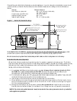
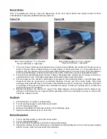
4.  Check the appearance of the burner flame (See Figure 11A and 11B on Page 13). 


5.  Be sure circulating air fan is operating and verify proper airflow through duct furnace 


6.  Return thermostat or heat controller to normal setting. 


If any of the original wiring needs to be replaced it must 

be replaced with wiring materials suitable for 105

o

C. 


CAUTION! 

Содержание HH SERIES

Страница 1: ...or other flammable vapors and liquids in the vicinity of this or any other appliance WHAT TO DO IF YOU SMELL GAS Do not try to light any appliance Do not touch any electrical switch do not use any ph...

Страница 2: ...rt up 11 Manifold Pressure Adjustment 11 Gas Valves 12 Burner Flames 13 Shutdown 13 Normal Operation 13 Safety and Ignition Controls 14 Annual Maintenance Inspection 14 15 Installation Requirements Al...

Страница 3: ...ent and maintenance of the furnace installed Provide at least 36 0 9m clearance for removal of access panel 11 Filters and filter rack components rated 250 oF 121 oC or less must be located a minimum...

Страница 4: ...ces with vertical or horizontal top mounted burner trays to remove condensate from inside the heat exchanger Condensate drain lines must be connected if heater is located downstream of cooling section...

Страница 5: ...enance Gas Supply Piping and Connections 1 Installation of piping must conform with local building codes and ordinances or in the absence of local codes with ANSI Z223 1 the National Fuel Gas Code In...

Страница 6: ...Outdoor Horizontal Venting Combustion Air Opening AHU Cabinet Rain Hood Optional Flue Gas flow unobtructed Comb Blwr Mesh Screen AHU Cabinet Combustion Air Inlet Cover Mesh Screen Rain Hood Optional O...

Страница 7: ...50 160 50 000 175 000 14653 51287 5 in 126 mm HMG200 400 HMD200 HHG200 360 200 000 400 000 58614 117228 6 in 152 mm HM A B 150 400 HHA150 400 150 000 400 000 43960 117228 6 in 152 mm HM A B G 500 600...

Страница 8: ...not exceed 50 ft 15 25m Equivalent length of 5 or 6 inch 90o elbows is 5 ft 1 5 m and for a 7 inch 90o elbow is 7 feet 2 13 m 45o Elbows are half of the equivalent length of 90o The vent system must...

Страница 9: ...pplied to systems for operation in separated combustion systems The furnace must be mounted with the burner section in a reasonably airtight vestibule compartment as these systems provide combustion a...

Страница 10: ...lent length of vent pipe and air supply is 50 ft Individual runs should be approximately same length Figure 9 Horizontal Venting Separated Combustion Exterior Wall 18 in 0 45m Above grade or expected...

Страница 11: ...es 10 Turn power on at disconnect switch 11 Set thermostat or controller to its highest position to initiate call for heat and maintain operation of unit 12 Draft inducer will run for a 15 to 30 secon...

Страница 12: ...ure 10B White Rodgers 36H Gas Valve Figure 10C Honeywell V8944 Gas Valve 1 8 NPT Inlet Pressure Tap 2nd Stage Hi Fire Manifold Pressure Adjustment 3 32 Allen Key 1st Stage Lo Fire Manifold Pressure Ad...

Страница 13: ...hanger tubes with stiff brush Poor flame characteristics can also be caused by undersized combustion air openings or flue gas recirculation into combustion air supply Increase air opening size or re d...

Страница 14: ...itions the unit is equipped with a fixed temperature high limit switch mounted on the vestibule panel This switch will shut off gas to the heater through the ignition control module before the air tem...

Страница 15: ...s valve to ensure that the gas valve seat is not leaking 6 Check wiring connections to be sure they are secure and inspect wiring for any deterioration 7 Label all wires prior to disconnection when se...

Страница 16: ...16 Page left blank Heatco Inc 50 Heatco Court Cartersville Ga 30120...

Отзывы: