Section 5-3
39
MLSM2003-01-03
Procedure 22
- Spark Module(s)
Step 1: Disconnect power supply
to range.
Step 2: Remove range’s back
panel (see Procedure 32)
Step 3: Test wiring and
connections to spark module,
particularly black, white and green
wires to ensure they are tightly
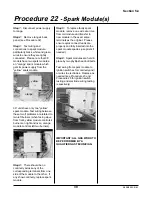
connected. Please note that 36”
models have two spark modules -
an “orange” spark module which
gets its power supply from the
“yellow” spark module,
30” units have only one “yellow”
spark module. Test wiring between
these two if problems are related to
two left burners (when facing stove
from front, yellow module controls 4
burners on right and oven, orange
module controls left two burners).
Step 4: There should be no
continuity across any of the
corresponding terminals from one
side of the module to the other. If
any show continuity, replace spark
module.
Step 5: To replace faulty spark
module, remove one wire at a time
from old module and transfer to
new module in the exact same
terminals as the original. Please
ensure quick connect leads are
properly and fully inserted into the
spark module spades (use pliers if
needed).
Step 6: Spark modules are held in
place by two phyllips head nut/bolts.
Test wiring from spark module to
ignition switches for continuity and/
or wires to electrodes. Replace as
needed (see Procedure 23 and
Procedure 28 for ignition switch
testing and electrode wiring testing
respectively)
IMPORTANT: ALL GAS WORK TO
BE PERFORMED BY A
QUALIFIED GAS TECHNICIAN.
yellow
orange
Содержание 3520
Страница 4: ...4 MLSM2003 01 03 PAGE LEFT BLANK ...
Страница 6: ...6 MLSM2003 01 03 PAGE LEFT BLANK ...
Страница 10: ...Section 3 10 MLSM2003 01 03 PAGE LEFT BLANK ...
Страница 57: ...Section 6 57 MLSM2003 01 03 Wiring Diagrams Models 3520 3525 ...
Страница 58: ...Section 6 58 MLSM2003 01 03 Wiring Diagrams Models 3620 3625 ...


