1
Installation & Operating Instructions
WSK300
Multifunction Wall Control
2101-915C 11/06
Hearth & Home Technologies disclaims any
responsibility for, and the warranty will be
voided by, the following actions:
• Installation and use of any damaged system
component.
• Modi
fi
cation of the system component.
• Installation other than as instructed by Hearth & Home
Technologies.
• Installation and/or use of any component part not
approved by Hearth & Home Technologies.
Any such action may cause a
fi
re hazard.
• Read, understand and follow these instructions for safe
installation and operation.
WARNING
Introduction
Printed in U.S.A. Copyright 2006
Hearth & Home Technologies Inc.
20802 Kensington Boulevard, Lakeville, MN 55044
The WSK300 multifunctional wall switch is designed to
control
fl
ame height, blower speed, and up to 2 other 110-
120 VAC auxiliary functions on your gas
fi
replace. Also,
the wall switch is equipped with thermostat functions
which can automatically control the temperature in the
room in which it is installed. The control is only for use
with the Intelli
fi
re system (IPI). However, the pilot function
can control the pilot
fl
ame as well. Electrical ratings for
the control box are 110 VAC, 60 Hz, and is required for
operation of this device.
Installation
1.
Locate placement of wall control. The wall control must
be located within 30 feet (within the line of sight) of the
fi
replace and 5 feet from the
fl
ooring. A maximum wire
length of 50 feet may be used.
Note: The electrical junction box provided with the
fi
replace
must be wired with 110 VAC before installing this kit. See
owners manual for details.
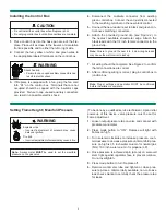
Shock Hazard
Do not provide any power to this unit until all
wiring is completed. Failure to do so may destroy
parts of this device and render it unusable, and
may lead to possible electrical shock.
Fire Hazard
Modi
fi
cation of any parts or installation of dama-
ged components will void the warranty, and you
may possibly cause a
fi
re hazard.
2.
Remove wall control from packaging material.
3.
Remove wall control back plate by pushing down on
two tabs located at top left and right of control face.
4.
Mount control box back on wall surface. Install two
screws at holes provided on wall control back at top
and bottom.
All wiring should be done by a quali
fi
ed electrician and
shall be in compliance with local codes and with the
National Electric Code ANSI/NFGA No. 70- current (in the
United States), or with the current CSA C22.1 CANADIAN
ELECTRIC CODE (in Canada).
WARNING
Note:
Whenever the
fi
replace is turned on, the
fl
ame size
will always be on HI for 75 seconds, then the control will set
the
fl
ame to the programmed setting.
Note:
The wall control is a three conductor, low voltage
control that requires a minimum of a 22 gauge wire. The
control is shipped with 18 feet of wire.
Note:
This wall control is designed to mount to a wall
junction box. To secure to wall properly ensure that a wall
stud is located behind wall. For exterior wall installations,
it is recommended that the junction box be sealed with
caulking material. This will minimize heat loss through
this location and improve the accuracy of the automatic
(thermostat) operation.
Note:
Ensure wires are connected to the correct color
coded locations on terminal block face. Red to red, green
to green, and white to white/yellow.
5.
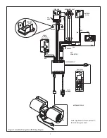
Connect red, green and white wires from the
fi
replace
control module to the terminal block located on the
back of the control face panel.
Placement of this wall switch may affect performance
or accuracy of the automatic (thermostat) control.
An assessment of the space should be done prior to
installation for optimal performance. See the installation
instructions section I for recommendations.


