02/04
4034-102 Rev F
27
HRV200PLUS INSTALLATION INSTRUCTIONS
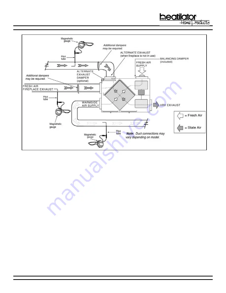
Figure 16 - Pitot Tube Balancing
Страница 1: ...con nected equipment NEVER install a ventilator in a situation where its normal operation lack of operation or partial failure may result in the back drafting or improper functioning of vented com bus...
Страница 2: ...V200PLUS is designed for climates where the heating season is typically longer than the cooling season The HRV is equipped with an aluminum core not allowing the transfer of moisture between the air s...
Страница 3: ...ted at 120VAC 1 4 Amps Air Filters Air filters are supplied in both the exhaust and supply air streams The filters are washable and easily removed for cleaning Automatic Defrost System The HRV200PLUS...
Страница 4: ...S M 9 3 4 C A S C s L 0 7 m f c 9 4 1 0 6 y c n e i c i f f E e l b i s n e S C 0 F 2 3 s L 0 7 m f c 9 4 1 5 5 y c n e i c i f f E e l b i s n e S C 5 2 F 3 1 s L 2 6 m f c 1 3 1 3 5 z H 0 6 C A V 0...
Страница 5: ...replace Causes unexpected Fresh Air Fireplace ignitions Fixed mesh screens screen door retainers must be used on the Caliber NXT Plus and the 6100 PLUS WARNING Removing the DEFC1 jumper allows the HRV...
Страница 6: ...nsure the DEFC1 jumper is installed on the HRV control board This jumper will disable the defrost logic in the HRV200PLUS 3 Fresh Air Fireplace Defrost When the HRV200PLUS system is installed in clima...
Страница 7: ...only Actual installation may vary slightly due to individual design preferences The illustrations and diagrams used throughout these installation instructions are not drawn to scale 1 Simplified Insta...
Страница 8: ...main living areas of the home bedroom family room Stale air drawn from furnace return HRV must be balanced 2 Partially Dedicated Installation a Exhaust Air Stale air drawn from key areas of the home...
Страница 9: ...102 Rev F 9 HRV200PLUS INSTALLATION INSTRUCTIONS x 3 Fully Dedicated Installation Stale air drawn from key areas of the home bathroom kitchen laundry Fresh air supplied to main living areas HRV must b...
Страница 10: ...ne that is switched by the safety disconnect switch The hot line black is the proper line to be switched To confirm the proper polarity use a voltmeter or test lamp to ensure there is no power after t...
Страница 11: ...ctly from outdoors Should be located upstream if there are prevailing winds from the exhaust outlet At least 3 9m below when within 10 3m of the exhaust weatherhood dryer vents or furnace exhaust medi...
Страница 12: ...T WORK FOR AIR DISTRIBUTION ALWAYS CONNECT TO THE SUPPLY DUCT WORK DOWNSTREAM OF THE CENTRAL FURNACE OR AIR HANDLER a Duct the Warmside Air Supply The HRV200PLUS recovers heat from the fireplace norma...
Страница 13: ...d in moderation if necessary The main supply and return lines to and from the HRV200PLUS must be 6 150mm minimum Branch lines to the individual rooms may be as small as 4 100mm but 5 125mm lines are p...
Страница 14: ...s CoolVent Flexible Pipe 1 air clearance to combustible materials Firestops Hangers and Accessories as Required a Fresh Air Fireplace Exhaust Guidelines 1 FAF must be vented with CoolVent flexible ins...
Страница 15: ...3 Direction of flow may include any combination horizontal vertical up or vertical down but must not form a trap for condensation to collect 4 Refer to Figures 7 9 for horizontal termination locations...
Страница 16: ...ower must be running when the ventilator is operating for this system to be effective The HRV200PLUS comes factory wired ready to allow installation and operation of the Alternate Exhaust Damper Assem...
Страница 17: ...02 04 4034 102 Rev F 17 HRV200PLUS INSTALLATION INSTRUCTIONS Figure 6 Typical Horizontal Termination Figure 5 Horizontal Termination...
Страница 18: ...Rev F 02 04 HRV200PLUS INSTALLATION INSTRUCTIONS Figure 7 Termination Cap Locations 2 Horizontal Termination Locations flue exhaust and fresh air inlets Figure 8 Alcove Clearances 9 Electrical Service...
Страница 19: ...paved driveway which is located between two single family dwellings and serves both dwellings M Clearance under veranda porch deck or balcony 12 inches 30 cm minimum Recommended 30 inches 76 cm for vi...
Страница 20: ...ort per the manufacturer s installation instructions Insure proper use of necessary flashing and firestop spacers as required by the vent manufacturer b Install a CoolVent Universal Adapter to the end...
Страница 21: ...02 04 4034 102 Rev F 21 HRV200PLUS INSTALLATION INSTRUCTIONS Figure 11 Typical Vertical Termination...
Страница 22: ...gs adjoining roof lines adverse conditions etc may create a need for a taller vent should down drafting occur Figure 12 Vent Height for Vertical Termination Roof Pitch H Min Ft Flat to 6 12 1 0 6 12 t...
Страница 23: ...in Figure 13 Frame the opening with the same sized lumber as used in the ceiling floor joist DO NOT pack insulation around the vent Assemble vent sections with three screws per joint WARNING RISK OF...
Страница 24: ...exibility for a variety of installations by providing one high blower speed option and three low blower speed options High Speeds LJK ODFN 224 219 209 194 174 Med HOORZ 155 155 145 120 89 Med Low OXH...
Страница 25: ...he home through basement ground contact areas Excessive negative pressure may also cause the back drafting of vented combustion equipment Read the Application Warning on the front of this manual Prior...
Страница 26: ...ighest reading on the gauge Then damper that air flow back to match the lower reading from the other duct The flows should now be balanced Actual air flow can be determined from the gauge reading The...
Страница 27: ...02 04 4034 102 Rev F 27 HRV200PLUS INSTALLATION INSTRUCTIONS Figure 16 Pitot Tube Balancing...
Страница 28: ...ed to a magnehelic gauge or other manometer capable of reading from 0 to 0 25 in 0 62 PA of water preferably to three digits of resolution Take readings from both exhaust ducts and the warmside air su...
Страница 29: ...resh air through the existing duct work 1 Fireplace Operating Modes Connector P9 a OFF Mode The HRV is idle until an input is sensed This is the normal standby state when the HRV Plus is powered but n...
Страница 30: ...The HRV returns to its previous state WARNING The Fresh Air Fireplace is used by the HRV200PLUS for normal defrosting of the aluminum core during cold weather ventilation operation This results in fi...
Страница 31: ...i t a r e p o h c t i w s e r u s s e r p e d i r r e v o o t t u p t u O C D V 2 1 s s e c o r p n o i t i n g i e h t f o s d n o c e s y t r i h t m o C d r a o b e c a l p e r i f e h t o t t u p...
Страница 32: ...tes then return to its normal mode e Intermittent Ventilation Mode Intermittent Ventilation Mode is activated when 12VDC is sensed at both the W and the O terminals The HRV operates on Low Speed Venti...
Страница 33: ...l a n i m r e T n e p O y l l a m r o N 7 Furnace Interface Operating Modes Connector P3 See Section L WIRING for wiring diagram Figure 23 a OFF Mode The furnace blower operates normally based on the...
Страница 34: ...34 4034 102 Rev F 02 04 HRV200PLUS INSTALLATION INSTRUCTIONS L WIRING 1 Fireplace Control Wiring Caliber NXT Plus 6100 Plus Figure 18 Caliber NXT Plus or 6100 Plus HRV Wired Together...
Страница 35: ...02 04 4034 102 Rev F 35 HRV200PLUS INSTALLATION INSTRUCTIONS 2 Fireplace Control Wiring Novus Plus 6000 Plus Figure 19 Novus Plus Control Wiring Figure 20 6000 Plus Control Wiring...
Страница 36: ...V200PLUS INSTALLATION INSTRUCTIONS Figure 21 Thermostat Control Wiring For integrated use with the central furnace and thermostat 3 HVAC System Thermostat Control Wiring use to interface HRV200PLUS wi...
Страница 37: ...02 04 4034 102 Rev F 37 HRV200PLUS INSTALLATION INSTRUCTIONS Figure 22 Ventilation Control Wiring 4 Ventilation Control Wiring Controls may vary...
Страница 38: ...4034 102 Rev F 02 04 HRV200PLUS INSTALLATION INSTRUCTIONS 5 Furnace Interface Wiring Figure 23 Furnace Interface Wiring Note HRV board has a built in isolation relay to ensure thermostat compatibilit...
Страница 39: ...e clean filters wet or dry back into their positions against the core and return the clips to their original position 6 Slide the core back into its original position b Check and Clean Drain Lines 3 S...
Страница 40: ...air flow may also occur In new construction this may result within the first year due to heavy dust and may occur periodically over time depending on the outdoor conditions 1 Unplug the HRV200PLUS and...
Страница 41: ...86 ZLOO FRQWLQXH WR RSHUDWH QRUPDOO 7URXEOHVKRRW WKH V VWHP IRU LUHSODFH GRHV QRW LJQLWH SHU WKH 7URXEOHVKRRWLQJ XLGH 7KLV FRGH PD RFFXU GXULQJ ORZ DPELHQW WHPSHUDWXUH FRQGLWLRQV ZKHQ WKH ILUHSODFH L...
Страница 42: ...IRU VKRUW SHULRGV ZLOO UHPRYH DGGLWLRQDO PRLVWXUH 7LPHU RU IDQ FDQ EH DGGHG WR ZDVKURRP EDWKURRP H KDXVW RQGHQVDWLRQ VHHPV WR IRUP LQ WKH VSULQJ DQG IDOO 2Q KXPLG GD V DV WKH VHDVRQV FKDQJH VRPH FRQGH...
Страница 43: ...V SUHVVXUH VZLWFK LV SURSHUO FRQQHFWHG DQG ZLUHG 1RWH 7KH DOLE HU 1 7 3OXV 3OXV ZLOO RSHUDWH IRU WKLUW VHFRQGV ZKLOH SURYLQJ SURSHU GUDIW I VXIILFLHQW DLU IORZ LV QRW VHQVHG DW WKH IOXH FROODU DIWHU W...
Страница 44: ...9 H KDXVW EORZHU VHFWLRQ LV KRW WURXEOHVKRRW IRU SRRU DLU IORZ 7KH RYHU WHPSHUDWXUH VZLWFK RSHQV DW DQG FORVHV DW 7KH VZLWFK LV QRUPDOO FORVHG GXULQJ QRUPDO RSHUDWLRQ I WKH RYHU WHPSHUDWXUH VZLWFK LV...
Страница 45: ...59 ULOOHV UHDVH LOWHUV HDWKHUKRRGV HVFULSWLRQ 59 2XWVLGH HDWKHUKRRGV F Z VOHHYH DQG LQVXODWLQJ GXFW FROODU KLWH SODVWLF LQWDNH SHU FDUWRQ 59 LWFKHQ ULOOH IOLS IURQW ZLWK UHPRYDEOH JUHDVH ILOWHU 5HSODF...
Страница 46: ...59 59 59 7 59 7 59 8SSHU ORZHU KHHO RUH VVHPEO OXPLQXP 7 LOWHU OLS HVFULSWLRQ 0RWRU ZLWK DSDFLWRU ORZHU RXVLQJ 6HW RZHU ORZHU KHHO OXPLQXP 0HVK LOWHU HIW UDLQ 3DQ LUFXLW RDUG 2SWLRQDO HIURVW VVHPEO LW...
Страница 47: ...Fresh Air Inlets 18 Fresh Air Supply 11 Fresh Air Supply Ducting Install 12 Frost 5 Fully Dedicated Installation 9 Furnace Interface Control 29 Operating Modes 33 Wiring 38 G Gas Fireplace 2 Gas Furn...
Страница 48: ...repairs 4 environmental conditions additional air handling devices such as exhaust fans or forced air furnaces or other causes 5 interconnection with other appliances such as central vacuums or cloth...