background image

6

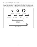
#8 x 3/4" Screw

(2)–4 

3/8" Star 

Washer (13)–6

5/16" Star 

Washer (11)–14

#10 x 3/4" Screw 

(9)–2

3/8" x 4" Screw (7)–6 

#8 x 1/2" Silver 

Screw (10)–1

#8 x 1/2" 

Screw (1)–12

#10 Star

Washer (5)–2 

5/16" x 2 1/2"

Screw (28)–4 

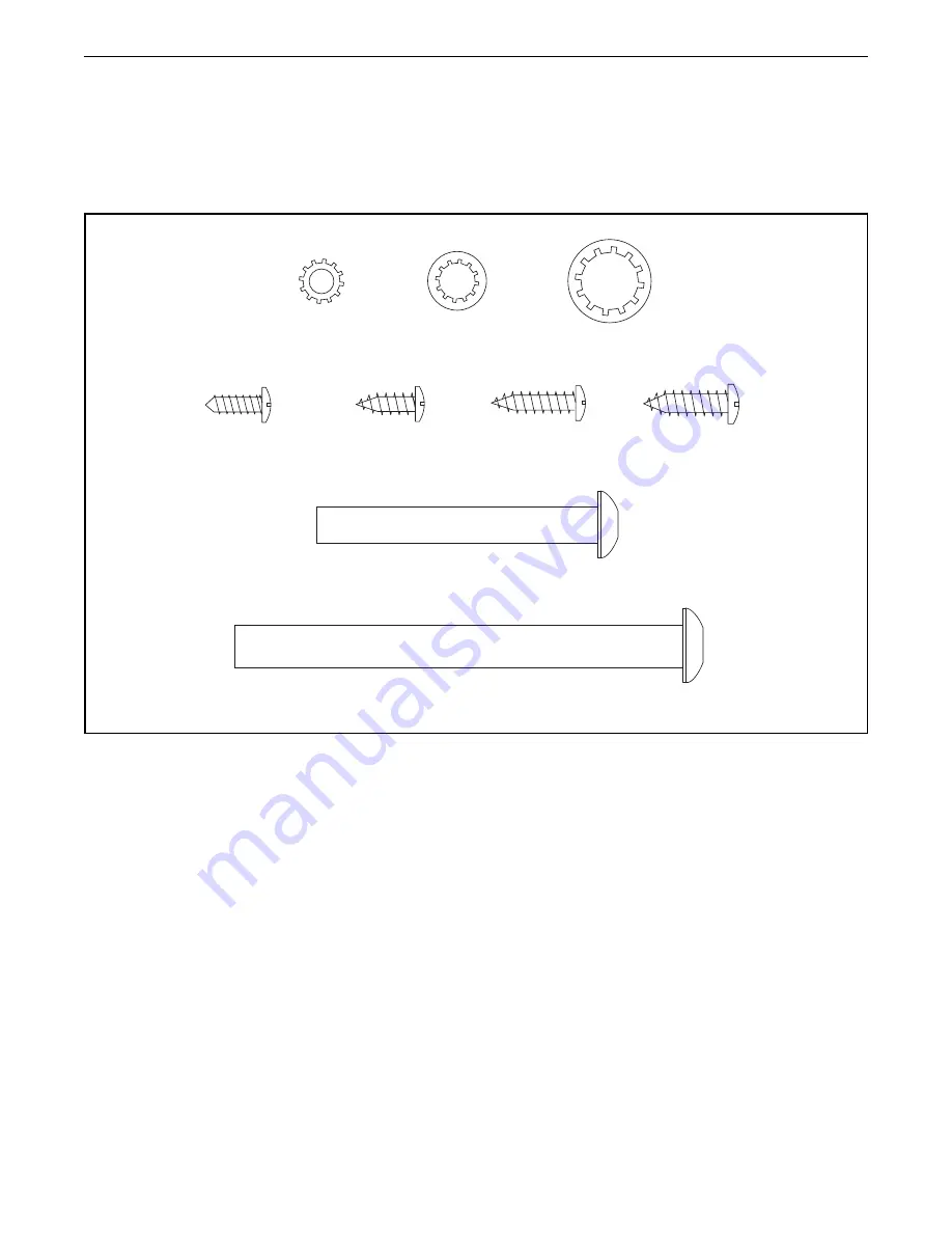
PART IDENTIFICATION CHART

Use the drawings below to identify small parts used for assembly. The number in parentheses below each draw-

ing is the key number of the part, from the PART LIST near the end of this manual. The number following the key 

number is the quantity used for assembly. 

Note: If a part is not in the hardware kit, check to see whether it is 

preattached. Extra parts may be included.

Содержание H200T HETL14915.0

Страница 1: ...future reference USER S MANUAL www iconeurope com CUSTOMER SERVICE UNITED KINGDOM Call 0330 123 1045 From Ireland 053 92 36102 Website www iconsupport eu E mail csuk iconeurope com Write ICON Health F...

Страница 2: ...E YOU BEGIN 5 PART IDENTIFICATION CHART 6 ASSEMBLY 7 THE CHEST HEART RATE MONITOR 18 HOW TO USE THE TREADMILL 19 HOW TO FOLD AND MOVE THE TREADMILL 28 MAINTENANCE AND TROUBLESHOOTING 29 EXERCISE GUIDE...

Страница 3: ...hed circuit No other appliance should be on the same circuit When replacing the fuse in the power cord adapter insert an ASTA approved BS1362 13 amp fuse into the fuse carrier 13 If an extension cord...

Страница 4: ...frame securely in the storage position 25 Never insert any object into any opening on the treadmill 26 Inspect and properly tighten all parts of the treadmill regularly 27 DANGER Always unplug the pow...

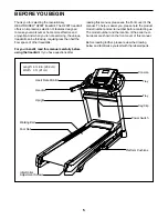
Страница 5: ...If you have questions after reading this manual please see the front cover of this manual To help us assist you please note the product model number and serial number before contacting us The model n...

Страница 6: ...RT IDENTIFICATION CHART Use the drawings below to identify small parts used for assembly The number in parentheses below each draw ing is the key number of the part from the PART LIST near the end of...

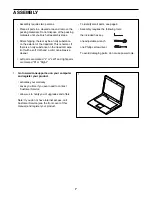
Страница 7: ...rts are marked L or Left and right parts are marked R or Right To identify small parts see page 6 Assembly requires the following tools the included hex key one adjustable wrench one Phillips screwdri...

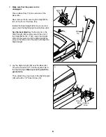
Страница 8: ...Right Upright 90 securely around the end of the Upright Wire 81 Then insert the Upright Wire into the lower end of the Right Upright as you pull the other end of the wire tie through the Right Uprigh...

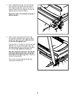
Страница 9: ...e of the Base 94 Hold the Right Upright 90 against the Base Make sure not to pinch the Upright Wire 81 Insert two 3 8 x 4 Screws 7 with two 3 8 Star Washers 13 into the Right Upright 90 and partially...

Страница 10: ...the Right Base Cover onto the Right Upright 90 Do not press the Base Covers into place yet 82 90 83 6 89 4 7 Identify the left handrail assembly B Attach the left handrail assembly B to the Left Upri...

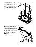
Страница 11: ...Wire 81 Then remove and discard the indicated screw C 28 11 D 90 81 8 64 18 41 93 E 9 9 Set the Console Base 64 face down on a soft surface to avoid scratching the Console Base If there are ties secur...

Страница 12: ...1 41 2 2 2 2 11 IMPORTANT To avoid damaging the Pulse Crossbar 93 do not use power tools and do not overtighten the 10 x 3 4 Screws 9 Orient the Pulse Crossbar 93 as shown Attach the Pulse Crossbar to...

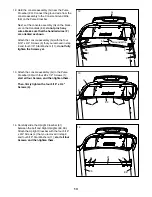
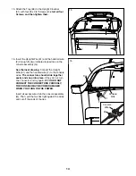
Страница 13: ...moved in step 9 and four 5 16 Star Washers 11 do not fully tighten the Screws yet 12 93 G 11 86 58 4 13 Attach the console assembly G to the Pulse Crossbar 93 with four 8 x 1 2 Screws 1 start all four...

Страница 14: ...o place If they do not turn one connector and try again IF YOU DO NOT CONNECT THE CONNECTORS PROPERLY THE CONSOLE MAY BECOME DAMAGED WHEN YOU TURN ON THE POWER Insert all excess wires into the console...

Страница 15: ...the Base 94 18 83 82 94 7 17 Insert the handrail wire F on the left side through the two indicated looped ties on the console assembly G and make the connection to the wire from the console Insert al...

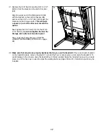
Страница 16: ...19 Note If the treadmill is assembled on a smooth surface it may roll forward during this step Raise the Frame 56 to the upright position Have a second person hold the Frame until step 21 is completed...

Страница 17: ...pages 30 and 31 Note Extra parts may be included 38 J 3 56 12 53 21 21 Remove the 5 16 Nut 12 and the 5 16 x 2 1 4 Bolt 3 from the bracket on the Latch Crossbar 38 Align the upper end of the Storage...

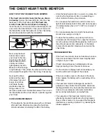
Страница 18: ...that may trap moisture Do not expose the heart rate monitor to direct sun light for extended periods of time and do not expose it to temperatures above 122 F 50 C or below 14 F 10 C Do not excessivel...

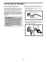
Страница 19: ...power cord into the socket on the treadmill 2 Plug the power cord into an appropriate outlet that is properly installed and earthed in accordance with all local codes and ordinances DANGER Improper co...

Страница 20: ...against other iFit users and access many other features To purchase an iFit module at any time go to www iFit com or call the telephone number on the front cover of this manual You can even listen to...

Страница 21: ...ton once Next press either the Incline decrease button or the lowest numbered incline button to set the treadmill to its lowest setting When the frame stops moving the treadmill is ready for use HOW T...

Страница 22: ...t of calories burned during that segment When the Calorie tab is selected the calorie display will show the approxi mate number of calories burned per hour As you exercise the workout intensity level...

Страница 23: ...in the matrix If you select a calorie workout the approximate num ber of calories you will burn will appear in the name of the workout 3 Start the workout Press the Start button or the Speed increase...

Страница 24: ...from the console See step 8 on page 23 HOW TO USE A SET A GOAL WORKOUT 1 Insert the key into the console See HOW TO TURN ON THE POWER on page 21 2 Set a calories distance time or pulse goal First pres...

Страница 25: ...or transmitter 3 Select a user If more than one user is registered you can switch users in the iFit main screen Press the increase and decrease buttons next to the Enter button to select a user 4 Sele...

Страница 26: ...w much of the race you have completed The other lines will show your top four competitors The end of the matrix represents the end of the race 7 Measure your heart rate if desired See step 6 on page 2...

Страница 27: ...ress the power switch into the reset position and insert the key into the console However when you remove the key the displays will remain lit although the buttons will not function If the demo mode i...

Страница 28: ...ave the treadmill in the storage position in temperatures above 85 F 30 C HOW TO MOVE THE TREADMILL Before moving the treadmill fold it as described at the left CAUTION Make sure that the storage latc...

Страница 29: ...f the switch has tripped wait for five minutes and then press the switch back in b Make sure that the power cord is plugged in If the power cord is plugged in unplug it wait for five minutes and then...

Страница 30: ...l per formance may decrease and the walking belt may become damaged Remove the key and UNPLUG THE POWER CORD Using the hex key turn both idler roller screws counterclockwise 1 4 of a turn When the wal...

Страница 31: ...few minutes Repeat until the walking belt is centered SYMPTOM The walking belt slips when walked on a First remove the key and UNPLUG THE POWER CORD Using the hex key turn both idler roller screws cl...

Страница 32: ...c Exercise If your goal is to strengthen your cardiovascular system you must perform aerobic exercise which is activity that requires large amounts of oxygen for prolonged periods of time For aerobic...

Страница 33: ...lles Stretch With one leg in front of the other reach forward and place your hands against a wall Keep your back leg straight and your back foot flat on the floor Bend your front leg lean forward and...

Страница 34: ...2 1 Left Foot Rail 43 1 Caution Decal 44 1 Walking Platform 45 1 Walking Belt 46 2 Belt Guide 47 1 Right Rear Foot 48 4 Cable Tie 49 1 Drive Roller Pulley 50 1 Magnet 51 1 Reed Switch Clip 52 1 Reed S...

Страница 35: ...4 Screw 108 2 Motor Bushing 109 1 8 Nut 110 1 8 x 3 4 Machine Screw 111 1 Electronics Bracket 112 1 Filter 113 1 Motor Isolator 114 1 Grounding Strap 115 1 Receptacle 116 2 Base Pad 117 1 Chest Sensor...

Страница 36: ...3 15 34 30 59 61 15 30 34 59 23 19 46 43 42 44 21 34 30 59 24 24 57 100 102 24 2 2 103 104 2 24 101 4 11 101 101 101 101 101 37 97 35 39 95 35 39 26 2 2 14 14 14 92 2 2 14 14 39 26 35 35 39 96 92 100...

Страница 37: ...37 66 65 102 102 102 40 2 68 75 2 2 73 72 2 2 2 78 24 24 24 68 68 2 67 67 33 29 69 33 70 16 71 33 33 71 32 2 106 10 114 10 115 76 8 68 EXPLODED DRAWING B Model No HETL14915 0 R0315A...

Страница 38: ...10 82 91 7 25 83 89 4 11 86 79 87 11 28 90 86 85 84 4 11 28 11 25 91 13 63 62 74 7 13 74 62 63 81 58 10 93 9 1 1 1 1 1 5 9 5 1 116 14 14 116 22 22 11 4 31 4 11 2 11 4 2 2 2 88 EXPLODED DRAWING C Mode...

Страница 39: ...39 2 2 41 41 2 99 64 1 1 36 1 1 1 2 2 2 27 18 80 98 2 2 2 2 118 117 EXPLODED DRAWING D Model No HETL14915 0 R0315A...

Страница 40: ...T and the EXPLODED DRAWING near the end of this manual ORDERING REPLACEMENT PARTS This electronic product must not be disposed of in municipal waste To preserve the environment this product must be re...

Отзывы: