background image

1

Hearth & Home Technologies  •  LOGS-60 Installation Instructions  •  2321-948 Rev. D  •  10/15

CAUTION: 

Logs are fragile, handle with care.

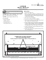
LOGS-60

MODELS: MEZZO

1600

• Installation Instructions  •

CAUTION! Risk of Cuts or Abrasions. 

Wear protective 

gloves and safety glasses during installation. 

Leave this manual with party responsible for use and 
operation.

Kit Components:
• Burner Port Fixture
• Ceramic Logs (8)
• Shoulder Screws (11)
• Self-Tapping Screws (13)

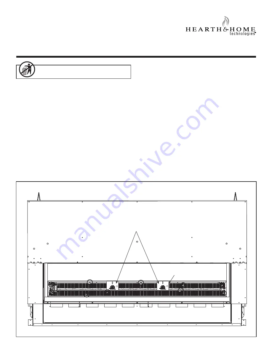
Figure 1. Burner Features - Shoulder Screw Locations

BURNER PORT FIXTURE LOCATIONS

(PILOT HOLES ON ROCK TRAY)

1 fixture included.  Use for two locations.  Discard after use.

1
2

5

4

3

10

11

8

7

6

9 (BEHIND FIXTURE)

INSTALLATION

1. Remove decorative front.
2. Remove 

fi

 xed glass assembly by unlatching the four

top spring latches. Allow the 

fi

 xed glass assembly to tilt

away from the 

fi

 replace and lift the 

fi

 xed glass assembly

up and out of the opening.

3. Lift burner rails out of appliance.
4. Remove any existing media from appliance.
5. Install eleven shoulder screws into pilot holes in media

tray.  Locations are indicated in Figure 1.

6. There are twelve burner port holes that must be plugged

in order to prevent sooting.  There are in two groups of
six holes.  A burner port 

fi

 xture will be installed on top of

the designated port holes.  See Figure 1 for location.

7. Locate the slot on the rock tray and align the burner port

fi

 xture over the pilot hole.

8. Place burner port 

fi

 xture over pilot hole and secure us-

ing a self-tapping screw.

Содержание MEZZO1600

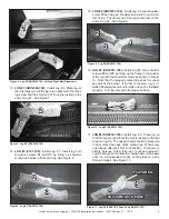
Страница 1: ...D FIXTURE INSTALLATION 1 Remove decorative front 2 Remove fixed glass assembly by unlatching the four top spring latches Allow the fixed glass assembly to tilt away from the fireplace and lift the fixed glass assembly up and out of the opening 3 Lift burner rails out of appliance 4 Remove any existing media from appliance 5 Install eleven shoulder screws into pilot holes in media tray Locations ar...

Страница 2: ...g 9 have holes located on the bottom that are used for placement on corresponding shoulder screws See Figure 5 Figure 5 Log Placement Holes Figure 3 Insert Screws into Burner Ports 10 Remove burner port fixture Discard Reinstall burner rails 9 Insert six self tapping screws into the 6 burner ports that lie within the burner port fixture rectangle holes See Figure 3 Move the burner port fixture to ...

Страница 3: ...r position Figure 7 Log 2 SRV2300 704 1 1 2 2 3 3 1 1 2 2 Figure 8 Log 3 SRV2331 708 15 LOG 4 SRV2331 706 Install Log 4 onto shoulder screw 6 by lining up shoulder screw with hole in bot tom of log The other end of the log should rest on the end of Log 3 See Figure 9 Figure 10 Log 5 SRV2331 704 Figure 6 Log 1 SRV2300 703 Left and Right Side Placement 1 1 1 1 Figure 9 Log 4 SRV2331 706 4 4 3 3 2 2 ...

Страница 4: ...th the appliance Fireplace will not function properly Delayed ignition may occur 18 Place media on media tray according to instructions in cluded with media kit Once the logs are installed there will not be room for all of the media originally installed The amount used should decrease by approximately five pounds 1 bag 19 Replace fixed glass assembly and decorative front on appliance NOTICE Do not...

Отзывы: