


021-DRF Rev B
DRC User Manual
5
Copyright © Enovation Controls – 2018
DRF Valve Controller
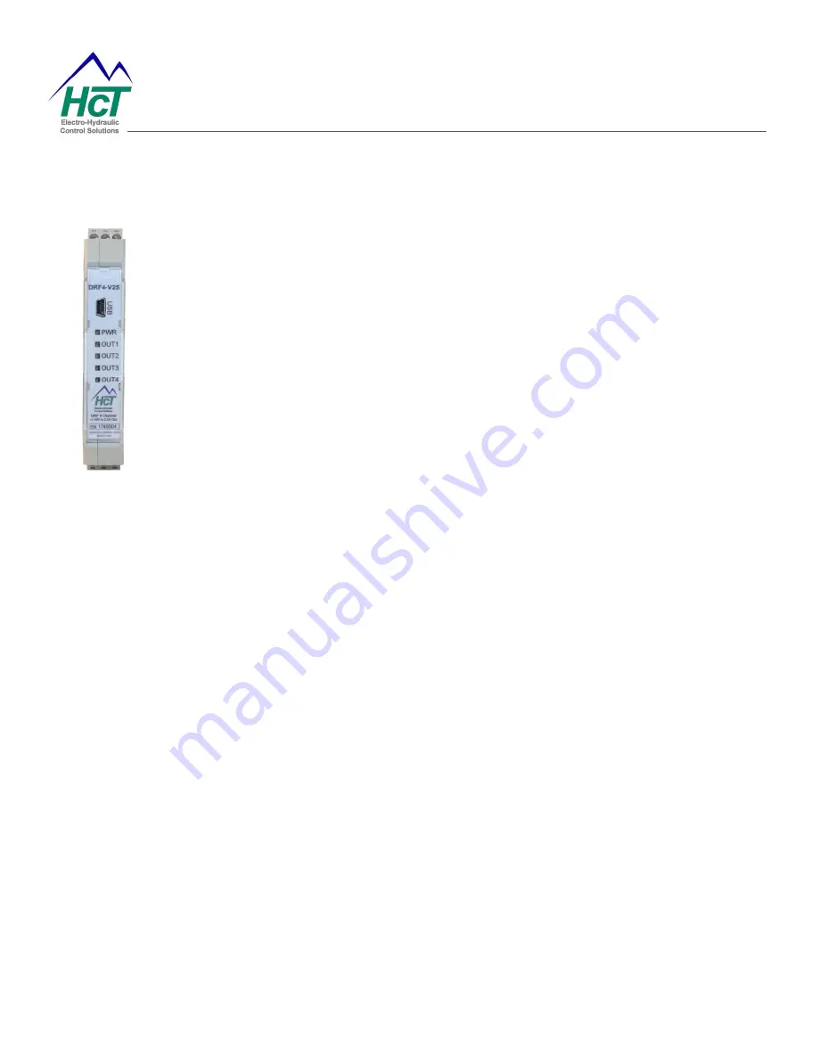
Physical Description
There are PWR LED and OUTx LEDs. For DRF-4, there are 5 LEDs. The PWR LED is
green when the applied voltage is within the operating range.
OUTx LEDs indicate current output for a given channel. The LEDs are yellow
and the
brightness will vary with the output current.
In the case of a fault the LEDs will flash red with a flash code. See Fault Status for
details.
The DRF communicates with the Graphical User Interface through the USB port.
When connected to a PC, the DR controller is recognized as a USB device with or
without power supply. However, it must be powered when configuring the settings.
User Interface
The DRF has a number of internal settings.
Users can open the Graphical User Interface to view, make changes and save the settings in a data file which can
be uploaded to any DRF controller.