HBM T21WN Скачать руководство пользователя страница 56

Zubehör

26

A4776-1.0


HBM: public

T21WN

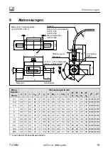
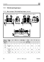
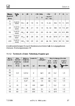
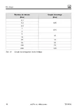
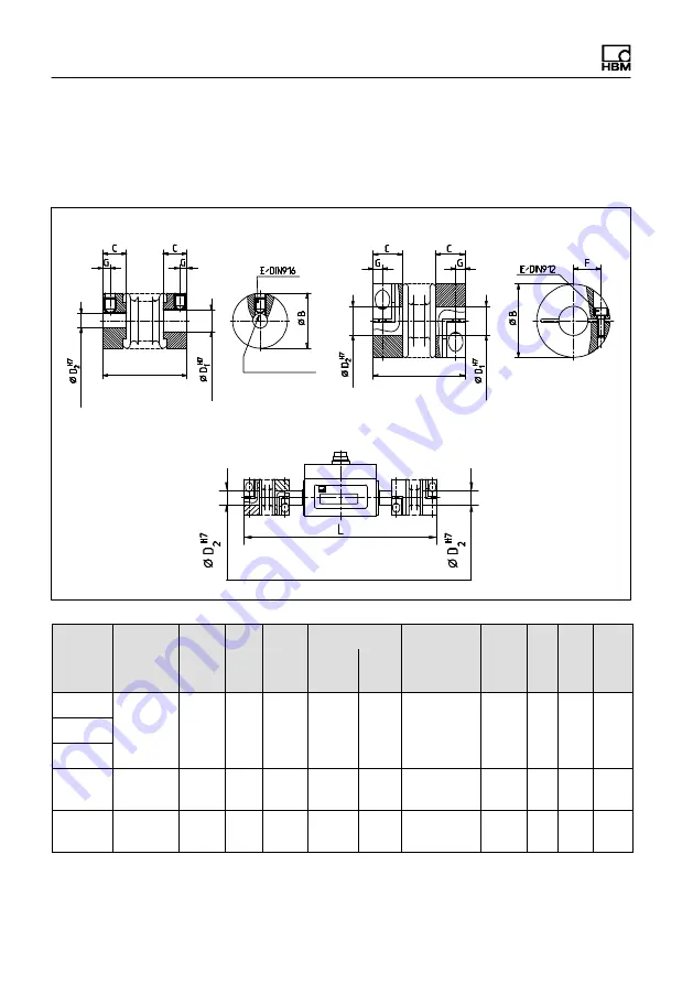
11.1 Faltenbalg‐Kupplungen

11.1.1 Abmessungen Faltenbalg‐Kupplungen (in mm)

Für Messbereiche 0,1 N

m...1 N

m

Für Messbereiche 2 N

m...200 N

m

Kundenseite

HBM-Messwelle

HBM-Messwelle

Kundenseite

A

A

Gesamtlänge

Messseite A

Antriebsseite B

A

B

Demontagenut

Mess­

bereich

(N·m)

Teile-

Nr.

A

j

B

C

j

D

1

 Side

j

D

2

E

F

G

L

A

B

variabel

min...max

0,1

3-4412.

0001

23

-1

15

6,5

6

8

3...9

M3

-

2

128

0,2

0,5

1

3-4412.

0002

25

-1

15

6,5

6

8

3...9

M3

-

2

132

2

3-4412.

0003

40

-1

25

13

6

8

3...12,7

M3

8

4

149

Содержание T21WN

Страница 1: ...Mounting Instructions Montageanleitung Notice de montage English Deutsch Fran ais T21WN...

Страница 2: ...product descriptions are for general information only They are not to be understood as a guarantee of quality or durability nderungen vorbehalten Alle Angaben beschreiben unsere Produkte in allgemein...

Страница 3: ...Mounting Instructions Montageanleitung Notice de montage English Deutsch Fran ais T21WN...

Страница 4: ...ings 8 4 3 2 Installation 8 5 Electrical connection 10 5 1 General instructions 10 5 2 Connector 10 5 3 Cable extension 12 5 4 Shielding design 13 6 Load carrying capacity 14 6 1 Measuring dynamic tor...

Страница 5: ...storage assembly and mounting and careful operation General dangers of failing to follow the safety instructions The transducer corresponds to the state of the art and is fail safe The transducer can...

Страница 6: ...nction Prevention of accidents In accordance with the health and safety regulations relevant to accident prevention once the operator has fitted the torque transducer a cover or cladding must be attac...

Страница 7: ...nts can lead to damage to property Emphasis See Italics are used to emphasize and highlight text and references to other chapters and external documents 2 2 Symbols on the product CE mark The CE mark...

Страница 8: ...sure static and dynamic torque and rotation speeds or angles of rotation for turning or static machine parts in any direction of rotation It is designed for small to medium sized torque such as that m...

Страница 9: ...N The permissible load limits given in the specifications see Page 20 are mandatory F Base mounting between two full couplings1 Front mounting full coupling on the right 2 belt drive on the left 1 HBM...

Страница 10: ...th couplings With the bellows type couplings the T21WN torque transducer can be oper ated in any installation position horizontal vertical or diagonal With vertical and diagonal operation make sure th...

Страница 11: ...Installation T21WN A4776 1 0 HBM public 9 Measuring range Tightening torque N m N m 0 1 0 35 0 2 0 5 1 0 75 2 5 1 5 10 20 14 50 35 100 75 200 120 Tab 4 1 Tightening torque of the clamping screws...

Страница 12: ...o be tightened firmly Do not route measurement cables in parallel to power lines and control circuits If this is not possible for example in cable ducts maintain a minimum dis tance of 50 cm and prote...

Страница 13: ...V 90 phase shifted GN H No function PK J Measurement signal ready for measurement GY K Control signal trigger GY PK L Torque measurement signal frequency output 5V 1 2 BU RD M Voltage reference for r...

Страница 14: ...es an internally galvanically isolated measurement signal The grounds must not be bridged directly on the transducer otherwise measurement errors may occur depending on the supply and analysis device...

Страница 15: ...stray fields of transformers motors and contactors Notice At the maximum rotational speed of 20 000 rpm the cable length is limited to maximum 10 m 5 4 Shielding design The cable shielding is connect...

Страница 16: ...ic torque measurement Notice The frequency of the dynamic torque must be lower than the natural frequency of the mechanical measuring system S The natural frequency f0 of the mechanical measuring syst...

Страница 17: ...ible dynamic loading 6 2 Rotation speed A slotted disk is installed on the loaded member It is sampled with an encoder in the enclosure The T21WN returns two square wave signals to the output offset b...

Страница 18: ...hannel A Pin G Channel B Pin B U 5 V t t Notice Torque transducer T21WN allows torque measurements up to a rotational speed of 20 000 rpm and rotational speed measurements up to 20 000 rpm When used w...

Страница 19: ...ed a positive output signal from 0 10 V or 15 kHz is present Direction of rotation The sign on the display indicates the direction of rotation With HBM measuring amplifiers the output voltage or displ...

Страница 20: ...Maintenance Torque transducer T21WN is largely maintenance free We recommend that the low friction special bearing should be replaced at the Darmstadt factory after approx 20 000 working hours The ca...

Страница 21: ...11 22 62 2 95 14 28 14 54 30 6 8 27 32 M3 6 M3 5 0 2 40 11 22 62 2 95 14 28 14 54 30 6 8 27 32 M3 6 M3 5 0 5 40 11 22 62 2 95 14 28 14 54 30 6 8 27 32 M3 6 M3 5 1 40 11 22 62 2 95 14 28 14 54 30 6 8...

Страница 22: ...ariation of the output signal 0 05 Temperature effect per 10 K in the nominal rated temperature range on the output signal relative to the actual value of the signal span Frequency output 0 1 Voltage...

Страница 23: ...M 1 Long term drift over 48 h mV 50 Cut off frequency 3 dB kHz 1 Residual ripple voltage output Group delay mVSS ms 100 1 0 Maximum modulation range Frequency output kHz 3 7 16 3 Voltage output V 11...

Страница 24: ...p delay s 3 for 1 5 m cable between T21WN and VK20A junction box without VK20A the group delay is dependent on the connected impedance cable analysis device Max measurable rotational speed rpm 20 0001...

Страница 25: ...n 1000 Duration ms 3 Acceleration half sine m s2 650 Vibration testing per EN 60068 2 6 IEC 68 2 6 1982 Frequency range Hz 5 65 Duration h 1 5 Acceleration amplitude m s2 50 Load limits 1 Torque limit...

Страница 26: ...0 G 6 3 1 Dependent on the nominal rated torque 2 Each type of irregular stress bending moment lateral or longitudinal force exceeding nominal rated torque can only be permitted up to its specified st...

Страница 27: ...1 Accessories S Transducer connection cable 5 m long order no 3 3301 0158 S Transducer connection cable 10 m long order no 3 3301 0159 S Cable socket 12 pin linkage order no 3 3312 0268 S Terminal box...

Страница 28: ...anges 2 N m 200 N m Customer side HBM transducer shaft HBM transducer shaft Customer side A A Overall length Measuring side A Drive side B A B Disassembly slot Meas range N m Part No A jB C jD1 Side j...

Страница 29: ...M10 27 11 300 200 3 4412 0008 109 2 110 35 26 26 24 56 M12 39 13 318 11 1 2 Specifications for bellows type couplings Meas Range N m Torque coupling TKmax N m Mass moment of inertia kg cm2 Weight g To...

Страница 30: ...pring stiffness Material hub and fixing ring Tightening torque clamping screws N m axial N mm radial N mm N m 0 1 13 4 47 7 Aluminum 0 35 0 2 0 5 1 27 4 84 3 0 75 2 20 6 88 0 75 5 33 3 389 1 5 10 20 5...

Страница 31: ...Mounting Instructions Montageanleitung Notice de montage English Deutsch Fran ais T21WN...

Страница 32: ...nbaulage mit Kupplungen 8 4 3 2 Einbau 8 5 Elektrischer Anschluss 10 5 1 Allgemeine Hinweise 10 5 2 Anschlussstecker 10 5 3 Kabelverl ngerung 13 5 4 Schirmungskonzept 13 6 Belastbarkeit 14 6 1 Messen...

Страница 33: ...ansport fachgerechte Lagerung Aufstellung und Mon tage sowie sorgf ltige Bedienung voraus Allgemeine Gefahren bei Nichtbeachten der Sicherheitshinweise Der Aufnehmer entspricht dem Stand der Technik u...

Страница 34: ...ertraut sind und ber die ihrer T tigkeit entsprechende Qualifikationen verf gen Unfallverh tung Entsprechend den einschl gigen Unfallverh tungsvorschriften der Berufsge nossenschaften ist nach der Mon...

Страница 35: ...Folge haben kann Hervorhebung Siehe Kursive Schrift kennzeichnet Hervorhebungen im Text und kennzeichnet Verweise auf Kapitel Bilder oder externe Dokumente und Dateien 2 2 Auf dem Ger t angebrachte Sy...

Страница 36: ...sche und dynamische Drehmo mente und Drehzahlen oder Drehwinkel an drehenden oder ruhenden Maschi nenteilen bei beliebiger Drehrichtung Sie sind konzipiert f r kleine bis mittlere Drehmomente wie sie...

Страница 37: ...aten siehe Seite 20 angegebenen zul ssigen Belas tungsgrenzen sind unbedingt einzuhalten F Fu montagezwischen zwei Vollkupplungen1 Stirnmontage rechts Vollkupp lung 2 links Riementrieb 1 HBM Zubeh r F...

Страница 38: ...esser mit j6 Toleranz ausf hren damit sich die Vorzugs passung H7 j6 ergibt 4 3 1 Einbaulage mit Kupplungen Die Drehmoment Messwelle T21WN kann mit den Faltenbalg Kupplungen in beliebiger Einbaulage h...

Страница 39: ...Querkr fte sowie Grenzbiegemomente der Drehmoment Messwelle nicht berschritten werden Beim Anziehen der Spannschrauben die Kupplung am Klemmelement festhal ten Messbereich Anziehdrehmoment N m N m 0 1...

Страница 40: ...st angezogen werden Verlegen Sie Messkabel nicht parallel zu Starkstrom und Steuerleitungen Ist dies nicht vermeidbar etwa in Kabelsch chten halten Sie einen Mindestab stand von 50 cm ein und ziehen S...

Страница 41: ...l Drehwin kel 5 V um 90 nacheilend gn H Nicht belegt rs J Messsignal Messbereit gr K Kontrollsignalausl sung gr rs L Messsignal Drehmoment Frequenzausgang 5V 1 2 bl rt M Spannungsreferenz Drehzahl Win...

Страница 42: ...n grad U U Abb 5 1 Anschlussschema T21WN Der Aufnehmer erzeugt intern ein galvanisch getrenntes Messsignal Die Mas sen d rfen nicht am Aufnehmer direkt gebr ckt werden da es sonst entspre chend der Ka...

Страница 43: ...tahlpanzerrohr und halten Sie einen m glichst gro en Abstand zu anderen Kabeln Meiden Sie Streufelder von Tra fos Motoren und Sch tzen Hinweis Bei maximaler Drehzahl von 20 000 1 min ist die Kabell ng...

Страница 44: ...statische Drehmomente durchgef hrte Kalibrierung gilt auch f r dy namische Drehmomentmessungen Hinweis Die Frequenz der dynamisch wirkenden Drehmomente muss kleiner als die Eigenfrequenz der mechanisc...

Страница 45: ...tgrenze Obere Drehmomentgrenze Abb 6 1 Zul ssige dynamische Belastung 6 2 Drehzahl Auf dem Verformungsk rper ist eine Schlitzscheibe installiert Diese wird mit einem Encoder im Geh use abgetatstet Die...

Страница 46: ...A Pin G Kanal B Pin B U 5 V t t Hinweis Die Drehmoment Messwellen T21WN erlauben Drehmomentmessungen bis zu einer Drehzahl von 20 000 min 1 und Drehzahlmessungen bis 20 000 min 1 Bei Verwendung mit Ku...

Страница 47: ...gersinn eingeleitet steht ein po sitives Ausgangssignal von 0 10 V bzw 15 kHz an Drehrichtung Das Vorzeichen der Anzeige gibt die Drehrichtung an Bei HBM Messverst r kern ist die Ausgangsspannung bzw...

Страница 48: ...Wartung Die Drehmoment Messwelle T21WN ist weitgehend wartungsfrei Wir emp fehlen die reibungsarmen Speziallager nach ca 20 000 Betriebsstunden im Werk Darmstadt wechseln zu lassen Bei dieser Gelegenh...

Страница 49: ...22 62 2 95 14 28 14 54 30 6 8 27 32 M3 6 M3 5 0 2 40 11 22 62 2 95 14 28 14 54 30 6 8 27 32 M3 6 M3 5 0 5 40 11 22 62 2 95 14 28 14 54 30 6 8 27 32 M3 6 M3 5 1 40 11 22 62 2 95 14 28 14 54 30 6 8 27 3...

Страница 50: ...DIN 1319 be zogen auf die Ausgangs signal nderung 0 05 Temperatureinflu pro 10 K im Nenn temperaturbereich auf das Ausgangssignal bezogen auf den Istwert der Signalspanne Frequenzausgang 0 1 Spannungs...

Страница 51: ...48 h mV 50 Grenzfrequenz 3 dB kHz 1 Restwelligkeit Spannungsausgang Gruppenlaufzeit mVSS ms 100 1 0 Maximaler Aussteuer bereich Frequenzausgang kHz 3 7 16 3 Spannungsausgang V 11 11 Aufl sung Frequen...

Страница 52: ...A ohne VK20A ist die Gruppenlaufzeit abh ngig von der angeschlossenen Impe danz Kabel Auswerteger t Maximal me bare Drehzahl min 1 20 0001 Allgemeine Angaben EMV St rfestigkeit nach EN61326 1 Tabelle...

Страница 53: ...gung Halbsinus m s2 650 Vibrationsbest ndigkeit Pr fsch rfegrad nach DIN IEC 68 Teil 2 6 IEC 68 2 6 1982 Frequenzbereich Hz 5 65 Dauer h 1 5 Beschleunigung Am plitude m s2 50 Belastungsgrenzen 2 Grenz...

Страница 54: ...IN ISO 1940 G 6 3 1 Abh ngig vom Nennmoment 2 Jede irregul re Beanspruchung Biegemoment Quer oder L ngskraft berschreiten des Nenndrehmomentes ist bis zu der angegebenen statischen Belastungsgrenze nu...

Страница 55: ...11 Zubeh r S Aufnehmer Anschlusskabel 5 m lang Bestell Nr 3 3301 0158 S Aufnehmer Anschlusskabel 10 m lang Bestell Nr 3 3301 0159 S Kabeldose 12polig Binder Bestell Nr 3 3312 0268 S Klemmenkasten Best...

Страница 56: ...ereiche 2 N m 200 N m Kundenseite HBM Messwelle HBM Messwelle Kundenseite A A Gesamtl nge Messseite A Antriebsseite B A B Demontagenut Mess bereich N m Teile Nr A jB C jD1 Side jD2 E F G L A B variabe...

Страница 57: ...00 3 4412 0008 109 2 110 35 26 26 24 56 M12 39 13 318 Anschlussbohrungen D2 nach Kundenwunsch innerhalb der angegebenen Grenzen Bohrungstoleranz H7 11 1 2 Technische Daten Faltenbalg Kupplungen Mess b...

Страница 58: ...m rad Gewicht g Massen tr gheits moment kg cm2 Dreh moment Kupplung TKmax N m Mess bereich N m 100 150 20 1600 141 2 0 15 1 5 200 300 40 3800 157 2 0 15 1 5 Messbereich Federsteife Werkstoff Nabe und...

Страница 59: ...Mounting Instructions Montageanleitung Notice de montage English Deutsch Fran ais T21WN...

Страница 60: ...ements 8 4 3 2 Montage 8 5 Raccordement lectrique 11 5 1 Remarques g n rales 11 5 2 Prise de raccordement 11 5 3 Rallonge de c ble 14 5 4 Concept de blindage 14 6 Capacit de charge 15 6 1 Mesure de co...

Страница 61: ...montage appropri s ainsi qu une utilisation soigneuse Risques g n raux en cas de non respect des consignes de s curit Le capteur est conforme au niveau de d veloppement technologique actuel et pr sen...

Страница 62: ...s correspondantes Travail en toute s curit Conform ment aux instructions de pr vention contre les accidents dans ce domaine il est n cessaire apr s le montage des couplem tres arbre de torsion par l e...

Страница 63: ...as respect es peut avoir pour cons quence des d g ts mat riels Mise en valeur Voir Pour mettre en valeur certains mots du texte ces derniers sont crits en italique 2 2 Marquages utilis s sur le produi...

Страница 64: ...es et vitesses ou angles de rotation statiques et dynamiques sur des pi ces de machines immobiles ou en rotation quel que soit le sens de rotation Il est con u pour des couples faibles moyens tels que...

Страница 65: ...cter les limites de charge admissibles sp cifi es dans les caract ristiques voir page 21 F Montage sur la base entre deux accou plements complets1 Montage frontal accouplement complet droite 2 pignon...

Страница 66: ...ol rer le diam tre de l arbre en j6 afin d obtenir le type conseill H7 j6 4 3 1 Position de montage en cas d utilisation d accouplements Le couplem tre arbre de torsion T21WN avec accouplements souffl...

Страница 67: ...e montage avec accouplement il ne faut pas d passer les forces axiales et transverses admissibles ainsi que les moments de flexion limites du couplem tre arbre de torsion Lors du serrage des vis de br...

Страница 68: ...Montage 10 A4776 1 0 HBM public T21WN Etendue de mesure Couple de serrage N m N m 0 1 0 35 0 2 0 5 1 0 75 2 5 1 5 10 20 14 50 35 100 75 200 120 Tab 4 1 Couple de serrage des vis de bridage...

Страница 69: ...us ne devez pas poser les c bles de mesure en parall le avec des lignes de courant fort et de commande Si cela n est pas possible par ex dans des puits c bles observez la distance minimum de 50 cm et...

Страница 70: ...e H Libre rs J Signal de mesure Pr t mesu rer gr K D clenchement du signal de controle gr rs L Signal de mesure couple sortie fr quence 5 V 1 2 bl rg M R f rence de tension vitesse angle de rotation 3...

Страница 71: ...U U Fig 5 1 Sch ma de connexion du T21WN Le capteur g n re en interne un signal de mesure isol galvaniquement Les masses ne doivent pas tre shunt es directement au niveau du capteur car cela peut con...

Страница 72: ...que possible avec les autres c bles Eviter les champs de fuite provenant des transformateurs moteurs et contacteurs disjoncteurs Note la vitesse de rotation maximale de 20 000 tr min la longueur du c...

Страница 73: ...iques est galement valable pour les mesures de couples dynamiques Remarque La fr quence des couples agissant de mani re dynamique doit tre inf rieure la fr quence propre du montage de mesure m canique...

Страница 74: ...6 2 Vitesses de rotation limites Un disque fentes est install sur le corps de d formation Il est mesur l aide d un encodeur situ dans le bo tier Le T21WN d livre en sortie deux signaux carr s en quadr...

Страница 75: ...broche B U 5 V t t Note Les couplem tres arbre de torsion T21WN peuvent mesurer des couples jusqu une vitesse de 20 000 min 1 et mesurer des vitesses de rotation jusqu 20 000 min 1 En cas d utilisatio...

Страница 76: ...a un signal de sortie positif de 0 10 V ou 15 kHz Sens de rotation Le signe de l affichage indique le sens de rotation Dans les amplificateurs de mesure HBM la tension de sortie resp l affichage est...

Страница 77: ...retien Le couplem tre arbre de torsion T21WN est quasiment sans entretien Il est conseill de faire changer l usine de Darmstadt le palier sp cial sans frottement apr s env 20 000 heures de service Le...

Страница 78: ...y4 x4 0 1 40 11 22 62 2 95 14 28 14 54 30 6 8 27 32 M3 6 M3 5 0 2 40 11 22 62 2 95 14 28 14 54 30 6 8 27 32 M3 6 M3 5 0 5 40 11 22 62 2 95 14 28 14 54 30 6 8 27 32 M3 6 M3 5 1 40 11 22 62 2 95 14 28 1...

Страница 79: ...la variation du signal de sortie 0 05 Influence de la temp rature par 10 K dans la plage nominale de temp rature sur le signal de sortie rapport e la valeur effective de la plage de signal Sortie fr q...

Страница 80: ...ce de charge M 1 D rive long terme sur 48 h mV 50 Fr quence de coupure 3 dB kHz 1 Ondulation r siduelle sortie tension Temps de propagation de groupe mVcc ms 100 1 0 Plage de modulation maximale Sorti...

Страница 81: ...s min 1 0 R sistance de charge k 10 Temps de propagation de groupe s 3 pour 1 5 m de c ble entre le T21WN et le bo tier de raccordement VK20A sans VK20A le temps de propagation de groupe d pend de l i...

Страница 82: ...v rit selon EN 60068 2 27 IEC 68 2 27 1987 Nombre n 1 000 Dur e ms 3 Acc l ration demi sinuso de m s2 650 Tenue aux vibrations degr de s v rit selon EN 60068 2 6 IEC 68 2 6 1982 Plage de fr quence Hz...

Страница 83: ...quilibrage selon DIN ISO 1940 G 6 3 1 D pend du couple nominal 2 Chaque sollicitation m canique anormale moment de flexion force transverse ou longitudinale d passement du couple nominal n est autori...

Страница 84: ...ble de raccordement du capteur long 5 m N de commande 3 3301 0158 S C ble de raccordement du capteur long 10 m N de commande 3 3301 0159 S Prise femelle 12 p les Binder N de commande 3 3312 0268 S Bo...

Страница 85: ...ues de mesure 2 N m 200 N m C t client Arbre HBM Arbre HBM C t client A A Longueur totale C t mesure A C t entra nement B A B Rainure de d montage Etendue de mesure N m N de com mande A jB C jD1 C t j...

Страница 86: ...12 0007 93 2 82 28 26 26 19 40 M10 27 11 300 200 3 4412 0008 109 2 110 35 26 26 24 56 M12 39 13 318 11 1 2 Caract ristiques techniques des accouplements soufflet Etendue de mesure N m Couple d accou p...

Страница 87: ...m rad Poids g Moment d inertie kg cm2 Couple d accou plement TKmax N m Etendue de mesure N m 100 150 20 1600 141 2 0 15 1 5 200 300 40 3800 157 2 0 15 1 5 Etendue de mesure Rigidit lastique Mat riau...

Страница 88: ...www hbm com HBM Test and Measurement Tel 49 6151 803 0 Fax 49 6151 803 9100 info hbm com measure and predict with confidence A4776 1 0 7 2001 4776 HBM public...

Отзывы: