O8406-EN
2022-07
flashing
yellow
→
Warning
Observe the warning details on the Thermo-6 temperature control unit
controller.
flashing red
→
Fault
Observe the details of the fault on the control unit of the Thermo-6
temperature control unit.
4
Commissioning
When initially starting-up, all electrical connections must be checked.
The Gate-6 is turned on and off by connecting or disconnecting power
supply. All interface cables can be plugged in and out during operation
(hot-pluggable).
The HB-Therm units are configured by default to obtain IP addresses
automatically (DHCP server is available). For manual network
configuration, see chapter 6.
4.1
Procedure
1.
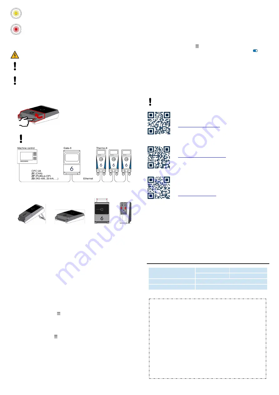
Hold both mounting tabs down and lift the cover up.
2.
Connect the control cable as shown in the following picture.
Use shielded Category 5 or higher cables for all Ethernet
connections.
3.
Connect the power cable to Gate-6.
4.
Position Gate-6 at the desired installation location in one of the possible
installation options (with/without bracket, screw-on or magnet mounting).
5.
Connect power supply to electrical outlet. As soon as the Gate-6 is
supplied with voltage, the LED starts to glow white.
→
After device initialization, the LED flashes green for the duration of the
connection setup (approx. 30 s). If a connection to a Thermo-6
temperature control unit cannot be established, the LED will
constantly flash green. In this case, go to point 6.
→
As soon as the connection to a Thermo-6 temperature control unit
has been established, the LED lights up green. Go to point 7.
6.
Check that the temperature control units are switched on and connected
correctly. If this is the case and it is still not possible to establish a
connection, the network settings on Gate-6 must be reset.
To do this, hold down the reset-button on the Gate-6 until the LED flashes
white briefly (approx. 3 s).
→ The network settings are reset.
If it is still not possible to establish a connection between Gate-6 and
Thermo-6, check the network setting on Thermo-
6 under 'Setting' →
'Remote c
ontrol' → 'Network'. The Network
configuration parameter must
be set to “Automatically”. Exit the Network menu. For more help if you still
can't connect, see chapter 6.
7.
Press the menu button on each connected Thermo-6 temperature
contr
ol unit →
press
'Setting' →
press
' Remote control' →
press 'Remote
address' and set.
8.
Optional only with addition
ZD
,
ZC
,
ZP
: Set the protocol on a connected
Thermo-6 temperature control unit.
Press the menu button on Thermo-6 temperature
control unit →
press
'Gate' →
press 'Protocol converter
' →
press 'Protocol' and set.
9.
Optional only for communication via
OPC UA
: For communication
between machine control, Gate-6 and Thermo-6 to work, all participants
must be in the same network. If a DHCP server is present, the Gate-6 as
well as the Thermo-6 must have received an IP address (current) not
equal to 169.254.xxx.xxx (the setting can be checked under 'Setting' →
'Remote control' → 'Network' for Thermo
-
6 and under 'Gate' → 'Settings'
→ 'Ne
twork Gate-6' for Gate-6). If this is the case, communication with the
machine controller should work. Otherwise, there is no DHCP server and
the network setting must be set manually. For more help, see chapter 6.
10. Press the menu button on each connected Thermo-6 temperature
control unit →
press
'Functions' → 'Remote
control' with slider (
) switch
on.
5
Application «e-cockpit»
e-cockpit is an app for smartphones and tablets. Data is accessed via Bluetooth
from the Gate-6 and the Thermo-6 temperature control units connected to it.
For information on connecting Gate-6 to the e-cockpit app and its functional
options, see chapter 6.
5.1
Download app «HB-Therm e-cockpit»
6
Knowledge
Go to Knowledge home page for general information.
http://hb.click/6-Knowledge-EN
Direct access to Knowledge for detailed assistance if the
connection cannot be established or if the network setting
needs to be made manually.
HB-Therm assumes no liability for damage caused by the use of the
e-cockpit application software that was downloaded outside of the
Google Play Store.
The app «HB-Therm e-cockpit» is available free of charge
from the Google Play Store.
Frequency band
WLAN
2,4 GHz / 5,0 GHz
Bluetooth
2,4 GHz
Overvoltage category
I
Degree of contamination
2
The nameplate is located on the back of the interface server Gate-6.
The following Information can be taken from the type plate:
-
Type
-
Unit number
-
Additional
-
Connected values
-
Year of manufacture
-
Protection class
-
Manufacturer
-
Service point
-
QR-Code (e-cockpit registration)


