Hayward MaxFlo VS 500 Скачать руководство пользователя страница 26


USE ONLY HAYWARD GENUINE REPLACEMENT PARTS 

Page 26 of 32 

MaxFlo VS 500 Variable Speed Pump


IS23510VSP  Rev-C 

9.


  Shaft Seal Change Instructions 

IMPORTANT SAFETY INSTRUCTIONS 

PLEASE READ AND FOLLOW ALL INSTRUCTIONS 

When servicing electrical equipment, basic safety precautions should always be observed including the following.  
Failure to follow instructions may result in injury. 


WARNING

 – To reduce risk of injury, do not permit children to use this product. 


     Disconnect all electrical power service to pump before beginning shaft seal replacement. 


Only qualified personnel should attempt rotary seal replacement.  Contact your local authorized Hayward Dealer or 

service center if you have any questions. 
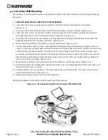
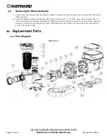
 

     Refer to 

Figure 10.1-1

 for pump component locations. 

 Exercise extreme care in handling both the rotating and the stationary sections of the two-part replacement seal. Foreign 
matter or improper handling will easily scratch the graphite and ceramic sealing surfaces. 

9.1.


Removing the Motor Assembly 

1.


Remove the four (4) 5/16" x 1.75" hex head bolts, which hold the motor assembly to the pump/strainer housing, 
using a 1/2" wrench or socket. 

2.


Slide the motor assembly out of the pump/strainer housing, exposing the diffuser. Remove the three (3) diffuser 
screws and pull the diffuser off of the seal plate to expose the impeller. 
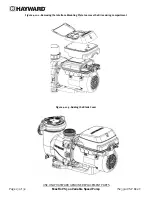
9.2.


Removing the Impeller 

3.


To prevent the motor shaft from turning, secure using a 5/16” hex wrench on the motor shaft through the fan 
shroud on the back of the pump. 

4.


Remove the impeller by rotating counterclockwise.  

9.3.


Removing the Ceramic Seat 

5.


Remove the spring seal assembly and seal plate from the motor by removing the four (4) 3/8” x 1” bolts that 
secure it to the motor, using a 9/16” wrench or socket.  

6.


Press the ceramic seat with rubber cup out of the seal plate.  If tight, use a small screwdriver to tap seal out. 

STOP

 - Clean all recesses & parts to be reassembled.  Inspect gaskets & replace if necessary. 
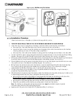
9.4.


Seal Installation 

7.


Clean and lightly lubricate the motor shaft and seal recesses in the seal plate with a dilute solution of non-
granulated liquid-type soap. Gently wipe the polished face of the ceramic seal with a soft cotton cloth.  Lubricate 
the rubber cup on the ceramic seat and press it firmly into the recess of the seal plate, with the polished ceramic 
surface facing out. 

8.


Reassemble the motor to the seal plate using the four (4) 3/8” x 1” bolts. Torque the bolts to 100 in-lbs. 

9.


Gently wipe the black, polished surface of the spring seal assembly with a soft cotton cloth.   

10.


Press the spring seal assembly onto the motor shaft, with the black polished surface facing the ceramic seat. 

9.5.


Replacing the Impeller and Diffuser 

11.


Screw the impeller onto the motor shaft in a clockwise direction.  Tighten snugly by holding motor shaft with 
wrench as noted in step #3.   

12.


Place the diffuser over the impeller and onto the seal plate, aligning the three (3) pins with the matching holes in 
the seal plate. Note: Flat side of diffuser rim will face up. Replace the three (3) diffuser screws and torque to 20 
in-lbs. 

Содержание MaxFlo VS 500

Страница 1: ...nt magnet motor The MaxFlo VS 500 pump is easily installed either as a programmable stand alone pump or with a Hayward or third party controller and features an easy to use digital control interface t...

Страница 2: ...ace Wall Mounting 12 4 13 Installation Procedure 14 5 Wiring Diagrams 15 5 1 Input Power Wiring Required 15 5 2 Wall Mounted Digital Control Interface Wiring Optional 15 5 3 External Relay Speed Contr...

Страница 3: ...ving the Ceramic Seat 26 9 4 Seal Installation 26 9 5 Replacing the Impeller and Diffuser 26 9 6 Replacing the Motor Assembly 27 10 Replacement Parts 27 10 1 Parts Diagram 27 10 2 Parts Listing 28 11...

Страница 4: ...National Electric Code NEC USE OF NON HAYWARD REPLACEMENT PARTS VOIDS WARRANTY ATTENTION INSTALLER THIS MANUAL CONTAINS IMPORTANT INFORMATION ABOUT THE INSTALLATION OPERATION AND SAFE USE OF THIS VAR...

Страница 5: ...using WARNING Failure to bond pump to pool structure will increase risk for electrocution and could result in injury or death To reduce the risk of electric shock see installation instructions and co...

Страница 6: ...ls must be in off position and filter manual air relief valve must be in open position Before starting pump all system valves must be set in a position to allow system water to return back to the pool...

Страница 7: ...r additional accessories Digital control interface that can be mounted in four different positions on the pump or removed and mounted on the wall Motor drive includes built in protection for high temp...

Страница 8: ...verify water is adequately flowing over the skimmer weirs Operate the pump at higher speeds for the shorter periods of time needed to operate a heater water feature etc 4 Installation and Wiring WARN...

Страница 9: ...ne to two layers of tape Wind the tape clockwise as you face the open end of the fitting beginning at the end of the fitting The pump suction and outlet ports have molded in thread stops Do NOT attemp...

Страница 10: ...8 4 mm2 No 6 AWG 13 3 mm2 for Canada solid copper bonding wire to the pressure wire connector provided on the motor housing and to all metal parts of swimming pool spa or hot tub and to all electrical...

Страница 11: ...face Orientation The Digital Control Interface can be rotated to any of four desired positions after installation by loosening the two screws securing the user interface to the motor drive lifting the...

Страница 12: ...the interface cable as shown in the Wall Mounted Digital Control Interface Wiring diagram shown in section 5 2 to the motor drive RS485 terminal block and user interface PCB Use multi conductor jacket...

Страница 13: ...ENUINE REPLACEMENT PARTS Page 13 of 32 MaxFlo VS 500 Variable Speed Pump IS23510VSP Rev C Figure 4 12 2 Removing the Interface Mounting Plate to access the Drive wiring compartment Figure 4 12 3 Addin...

Страница 14: ...ion 5 3 5 If the installation will use the remote stop feature of the drive connect the digital input terminals to the remote stop switch as shown in the Remote Stop Wiring diagram See section 5 4 6 W...

Страница 15: ...terface Wiring Optional Figure 5 2 1 Connection wire must be rated for a minimum of 300V and may be up to 500 feet in length Use removable 4 position terminal block connectors for wiring connection to...

Страница 16: ...e using relay contacts to select the speeds set in the Timer Menu see section 6 7 In addition to this section you may also consult the applicable pool control installation manual for electrical connec...

Страница 17: ...1 Prior to Start Up If it is necessary to perform a water pressure test prior to initial use to ensure plumbing system is functioning properly then the following criteria should be maintained for this...

Страница 18: ...r housing with water before starting motor ATTENTION Do NOT add chemicals to pool spa system directly in front of pump suction Adding undiluted chemicals may damage pump and voids warranty ATTENTION B...

Страница 19: ...scroll through the setup menus when pressed The and arrow buttons are used to move between displays and to select parameters to edit and the and arrow buttons are used to change parameters 3 Status LE...

Страница 20: ...ere X equals 1 through 4 c Speed X Speed where X equals 1 through 4 4 Diagnostics Menu see section 6 9 to view product diagnostic information a Display Firmware Revision b Drive Serial Number c Motor...

Страница 21: ...nutes in 30 second increments 10 Select Stand Alone or Relay Control Move to next menu item Note See section 5 3 for more detail 11 Enable or Disable Low Temp Operation Move to next menu item 12 Set t...

Страница 22: ...k Options are to run 7 days per week 5 days per week Monday thru Friday or on a single day Monday thru Sunday Each timer is set up in this same manner When the pump is powered and the timers are set u...

Страница 23: ...y updated without entering the Speeds Menu using the and arrow buttons to change the speed and then pressing the button to save the new speed setting 6 9 Diagnostic Menu Buttons Screen Used Comments 1...

Страница 24: ...g normal operation the above message will be displayed The pump will stop within several seconds and will remain stopped until Stop Resume is pressed a second time at which point the pump will resume...

Страница 25: ...volume blower when air purging the pump filter or piping ATTENTION Allowing the pump to freeze with water in it will void the warranty ATTENTION Use ONLY propylene glycol as antifreeze in your pool sp...

Страница 26: ...on the motor shaft through the fan shroud on the back of the pump 4 Remove the impeller by rotating counterclockwise 9 3 Removing the Ceramic Seat 5 Remove the spring seal assembly and seal plate from...

Страница 27: ...to disturb the diffuser gasket 14 Fasten assembly to pump strainer housing using the four 4 5 16 x 1 75 bolts Be sure housing gasket is in place and lubricated Replace if damaged Tighten bolts altern...

Страница 28: ...se Mount Screws 1 16 SPX1600Z52 Motor Support Base Mount Screws 1 17 SPX2700UNKIT Union Connector Kit Includes 2 Nuts Connectors Gaskets 1 18 SPX3400DR4 Motor Drive Display Cover Cover only 1 SPX3200L...

Страница 29: ...ull rpm s iii Open the housing cover and check for clogging or obstruction in suction Check the impeller for debris iv Remove and replace the shaft seal only if it is leaking Low Flow Generally 1 Clog...

Страница 30: ...Contact Hayward Technical Service for additional assistance Check System Processor failed Indicates that there is a problem with the processor in the motor drive and that the motor drive may need to b...

Страница 31: ...USE ONLY HAYWARD GENUINE REPLACEMENT PARTS Page 31 of 32 MaxFlo VS 500 Variable Speed Pump IS23510VSP Rev C 13 Warranty...

Страница 32: ..._______________________________ Type of Pool Concrete Gunite Vinyl Fiberglass Other_____________________________ New Installation Replacement Installation for In Ground Spa FCC Compliance Statement Th...

Отзывы: