


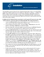


This Installation section will provide you with general instructions on how to set up the HPOE1
Adapter Kit with PoE-capable devices by walking you through two examples: 1. Installing the
HPOE1 Adapter Kit and connecting it to an IP camera (Hawking’s HNC290G Wireless-G
Network Camera will be used for this example), and 2. Installing the HPOE1 adapter kit and
connecting it to an access point (Hawking’s HWBA54G Wireless-G Multi-Function AP/Bridge
will be used for this example).
Installing the PoE Adapter Kit and connecting it to an IP camera (IP cameras are also called
“network cameras”; the terms will be used interchangeably in the instructions below.):
1.
Connect the
Data-In (LAN)
port on the PoE Injector to a LAN (Ethernet) port on a
router, switch, or hub using a standard RJ-45 Ethernet cable.
2.
Using another RJ-45 Ethernet cable, connect the
Power +
Data-Out
port on the PoE
Injector to the
Power + Data-In
port on the PoE Splitter.
3.
Plug the included 48V/0.4A power adapter into the PoE Injector’s
48V/0.4A Power-In
port. (You do not need to plug the power adapter into the wall outlet yet.)
4.
Connect the
Data-Out (LAN)
port on the PoE Splitter to the LAN (Ethernet) port on the
HNC290G Network Camera using a standard RJ-45 Ethernet cable. (Note: All network
cameras, whether wired or wireless, will have a LAN port.)
5.
Using the
DIP switch
that sits next to the
DC-Out
port, adjust the voltage setting on the
PoE Splitter to match that of the HNC290G IP camera (in this case, 12V). (In general, for
any PoE-capable network device that you connect to the PoE Splitter, you must adjust the
Splitter’s DIP switch to match the voltage setting of the network device. If you are unsure
of the network device’s voltage setting, you can find it in the device’s user’s manual or
datasheet, and sometimes on its packaging.) The PoE Splitter supports three voltage
settings: 5V, 7.5V, and 12V.
The default setting is 12V
. Note:
You must
adjust the DIP
switch to match the voltage setting on the network device
before
connecting the included
power link cable (described in the following step) and turning the power on.
6.
Next, connect one end of the included
Power Link
cable to the
DC Out
port on the PoE
Splitter. Then, connect the other end of the cable to the IP Camera’s power input port
on the back of the unit.
7.
Finally, ensure that all the connections are correct, and then plug the 48V/0.4A power
adapter into the wall outlet. The installation process is now complete. If you have
already installed and set up your IP camera, you can verify that the
PoE Adapter Kit–IP
Camera
system is working properly by typing the camera’s IP address into your web
browser’s address bar and viewing the live video.
10
Содержание HPOE1
Страница 1: ...1 ...


