background image

34
35
36
37
38
39
40
41
42
43
44
45
46
47
48
49
50
51
52
53
54
55
56
57
58
59
60
61
62
63
64
65

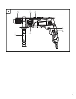
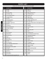
Gear #1
Flat key
Gear spindle drive
Rolling bearing
Spring lock
Steel ball
Knob spring
Speed adjusting knob
O seal ring
Cross recessed pan head tapping screws
Gauge
Handle
Assist handle
Nut
Pressing plate
Bolt
Handle cover
Cross Recess Head Screw
Shockproof gasket
Ball bearing
Rubber column
Brush
Brush holder
Armature
Stator assembly
Cable sheath
Cable
Cable pressing plate
Shell
Handle cover
switch
Lever

PARTS LIST

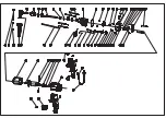
Please refer to the schematic drawing on the preceding pages

N

O.

DESCRIPTION

N

O.

DESCRIPTION

1
2
3
4
5
6
7
8
9
10
11
12
13
14
15
16
17
18
19
20
21
22
23
24
25
26
27
28
29
30
31
32
33

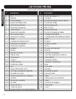
14

Screw
Chuck
Elastic collar;
Oil-catch ring
Tansmission shaft
Impact Spring
Gasket
Rolling bearing
Impact block
Reduction gear box
Gland
Dowel pin
Gear combination
Needle bearing
Pin
Knob
Knob spring
Steel ball
Spring shim
Pad
Wool felt
Ball bearing
Screw
Air seal ring
Cross Recess Head Screw
Spring washer
Bearing pressing plate
Support
Needle bearing
Washer
Wool felt 1
Wool felt 2
Retaining shaft rings(external)

ENGLISH

Содержание PT100321

Страница 1: ...her information please call our toll free number 1 866 206 0888 Enregistrez votre produit Nous vous invitons à enregistrer votre produit en ligne afin de faciliter les communications pour ce faire veuillez visiter le www outilshaussmann com CONSERVEZ CE GUIDE Vous aurez besoin de ce guide pour les règles de sécurité le fonctionnement et la garantie Conservez le avec votre facture d origine dans un...

Страница 2: ...A 1 2 3 5 6 4 7 1 ...

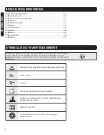
Страница 3: ...e sécurité Vitesse à vide Tension Protégez l outil électrique contre l humidité Assurez vous que l appareil le cordon d alimentation et la fiche sont en bon état Classe de sécurité II Jetez l emballage et l appareil de sorte à protéger l environnement TABLE DES MATIÈRES Symboles d avertissement p 2 Règles de sécurité p 3 Règles de sécurité additionnelles p 5 Application p 7 Données techniques p 7 ...

Страница 4: ...que de choc électrique c Manipulez le cordon avec soin Ne l utilisez pas pour porter tirer ou débrancher l outil électrique Assurez vous que le cordon est bien à l écart de toute chaleur de bords coupants ou de pièces en mouvement Des cordons endommagés ou enchevêtrés augmentent le risque de choc électrique d Si vous devez faire fonctionner un outil électrique dans un endroit humide utilisez un di...

Страница 5: ...avant de procéder à des réglages et remplacements d accessoires et de ranger l outil Ces mesures de sécurité préventives minimisent le risque de démarrage accidentel de l outil d Gardez l outil non utilisé hors de portée des enfants et ne laissez personne qui ne connaît pas cet outil ou ces instructions s en servir Les outils électriques laissés aux mains d utilisateurs inexpérimentés sont dangere...

Страница 6: ... et vos mains 6 Fixez correctement le matériel à percer Ne le maintenez jamais dans votre main ou sur vos genoux Un support instable peut faire coincer la mèche ce qui pourrait vous faire perdre le contrôle et vous blesser 7 Ne laissez jamais l interrupteur en position de marche Avant de brancher l outil vérifiez que l interrupteur est en position d arrêt Un démarrage accidentel peut provoquer des...

Страница 7: ...ns la pièce à travailler 16 Lors du retrait de la mèche de l outil évitez tout contact avec la peau et utilisez des gants de sécurité adéquats lors de la prise de la mèche ou de tout autre accessoire Après un usage prolongé il se peut que les accessoires soient chauds 17 Vérifiez que les clés de réglage et les clés sont retirées de la perceuse avant de mettre l outil en MARCHE Les clés de réglage ...

Страница 8: ...nt bien présentes Perceuse à percussion à 2 engrenages Poignée auxiliaire Si des pièces sont endommagées ou manquantes communiquez avec le Service à la clientèle aux coordonnées indiquées en première page de ce manuel Nomenclature des pièces La numérotation des pièces renvoie à l illustration de la page 1 figure A 1 Interrupteur de direction de rotation 2 Bouton de blocage en marche 3 Interrupteur...

Страница 9: ...iaire 8 Tirez pour faire sortir le guide de profondeur jusqu à ce que la distance entre l extrémité de la mèche et l extrémité de la butée d arrêt corresponde à la profondeur de perçage souhaitée Serrez la poignée auxiliaire avant de commencer à utiliser votre outil 2 Réglage de la profondeur de perçage Changement de mèche Embout de tournevis Utilisez toujours un porte embout universel pour les tr...

Страница 10: ...apidement sur l interrupteur marche arrêt 3 puis relâchez le Réglage de la vitesse fréquence de frappe 1 La vitesse le taux de frappe peut être réglé en fonction de la pression appliquée sur l interrupteur marche arrêt 3 2 Une légère pression sur l interrupteur marche arrêt 3 donne une vitesse un taux de frappe lent Une pression plus importante sur l interrupteur augmente la vitesse le taux de fra...

Страница 11: ...use de mèches 5 Nous recommandons l utilisation d un support de perçage lorsqu une précision parfaite est nécessaire 6 L étau d outil disponible comme accessoire permet d immobiliser en toute sécurité les pièces à travailler Cela permet d éviter la rotation de la pièce à travailler et tout accident qui pourrait en résulter Entretien et nettoyage évents propres Assurez vous régulièrement qu aucune ...

Страница 12: ...heure de l Est RONA se réserve le droit de réparer ou remplacer l outil défectueux à sa discrétion L usure normale y compris l usure des accessoires n est pas couverte par cette garantie Ce produit est garanti 36 mois s il est utilisé de façon normale Toute garantie est invalide si le produit a été utilisé en surcharge ou de façon non recommandée ou a fait l objet de négligence ou de réparations n...

Страница 13: ...cle de poignée Interrupteur Levier 1 2 3 4 5 6 7 8 9 10 11 12 13 14 15 16 17 18 19 20 21 22 23 24 25 26 27 28 29 30 31 32 33 12 Vis Mandrin Collet élastique Bague à barrage d huile Arbre de transmission Ressort de percussion Joint statique Roulement à aiguilles Bloc de percussion Réducteur de vitesse Bague Goupille de positionnement Mécanisme de vitesses Roulement à aiguilles Goupille Bouton Resso...

Страница 14: ......
Страница 15: ...ssing plate Shell Handle cover switch Lever PARTS LIST Please refer to the schematic drawing on the preceding pages NO DESCRIPTION NO DESCRIPTION 1 2 3 4 5 6 7 8 9 10 11 12 13 14 15 16 17 18 19 20 21 22 23 24 25 26 27 28 29 30 31 32 33 14 Screw Chuck Elastic collar Oil catch ring Tansmission shaft Impact Spring Gasket Rolling bearing Impact block Reduction gear box Gland Dowel pin Gear combination...

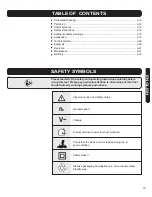
Страница 16: ...3 SAFETY SYMBOLS Please read all of the safety and operating instructions carefully before using this tool Please pay particular attention to all sections of this User Guide that carry warning symbols and notices Observe caution and safety notes No load speed Voltage Protect electrical power tool from moisture Check that the device mains lead and plug are in good condition Safety class II Dispose ...

Страница 17: ... Use of a GFCI device reduces the risk of electric shock e When operating a power tool outside use an outdoor extension cord marked W A or W These cords are rated for outdoor use and reduce the risk of electric shock f Do not use the equipment close to flammable objects 3 Personal safety a Stay alert watch what you are doing and use common sense when operating a power tool Do not use a power tool ...

Страница 18: ...nt or binding of moving parts breakage of parts and any other condition that may affect the power tool s operation If damaged have the power tool repaired before use Many accidents are caused by poorly maintained power tools f Use the power tool accessories etc in accordance with these instructions taking into account the working conditions and the work to be performed Use of the power tool for op...

Страница 19: ...not wrap the cord around your arm or wrist If the cord becomes entangled with the spinning bit it could entrap you causing serious personal injury 9 Position yourself to avoid being caught between the tool or side handle and walls or posts Should the bit become bound or jammed during the work the reaction torque of the tool could crush your hand or leg 10 If the bit becomes bound in the work piece...

Страница 20: ...n a well ventilated area and work with approved safety equipment and work with approved safety equipment such as those dust masks that are specially designed to filter out microscopic particles APPLICATION Read all safety warnings and all instructions Failure to follow the warnings and instructions may result in electric shock fire and or serious injury Intended Use The power tool is intended for ...

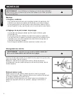
Страница 21: ...r clockwise direction rotate it to the desired position and lock it in place by turning it clockwise 8 2 Adjusting the Drilling Depth The required drilling depth can be set with the depth gauge 6 To adjust the depth gauge 6 loosen the auxiliary handle 8 Pull out the depth gauge until the distance between the tip of the drill bit and the tip of the depth stop corresponds with the desired drilling d...

Страница 22: ...3 actuated Right Rotation forward rotation For drilling and driving in screws push the rotational direction switch 1 through to the left stop Left Rotation reverse rotation For loosening and unscrewing screws and nuts press the rotational direction switch 1 through to the right stop Switching on and off 1 To start the power tool press the On Off switch 3 and keep it pressed 2 To lock the pressed O...

Страница 23: ... running it for approx 3 minutes at maximum speed with no load 2 Use carbide tipped drill bits when working in concrete masonry and brick wall 3 For drilling in metal use only perfectly sharpened HSS drill bits HSS High Speed Steel 4 Twist bits from 2 5 10 mm can be easily sharpened with a drill bit sharpener 5 We recommend the use of a drill stand for work where absolute precision is required 6 T...

Страница 24: ...od of 36 months from the date of purchase This guarantee does not affect your statutory rights In case of any malfunction of your tool failure missing part etc please contact one of our service technicians at our toll free service line at 1 866 206 0888 from 8 AM to 6 PM Monday to Friday Eastern time RONA reserves the right to repair or replace the defective tool at its discretion Normal wear and ...

Отзывы: