4 Install
12
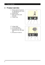
7. If necessary, connect the
signal line to the signal
socket.
• The discharging power
pack can be cycled via
the signal socket.
Configuration of the signal
socket:
A External control voltage
or
B External clock switch
Pin 1
External control
voltage (square
wave signal, 1 kHz,
10 V, positive)
Pin 2
0 V
Pin 3
not used
Pin 4
not used
Pin 5
Clock switch connection
Pin 6
Clock switch connection
PE
Shield Ground/signal ground
NOTE:
The discharging power pack only supplies voltage if the signal line
is connected or the jumper plug is screwed on.
In order to avoid a malfunction while the signal line is connected,
only one time-relay control unit may be connected. Either connect
the external control voltage or the external clock switch.
8. The discharging power pack is ready for operation.
Содержание 01.7908.005
Страница 2: ......
Страница 22: ......
Страница 23: ......
Страница 24: ...EN SL SLC MT v03gb docx V03 22 01 2019 D 0332 GB made by...


