GU641A Controller Operation Manual
42
8. Installation Guide
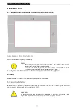
8.1 The cutout dimensional drawing installed on panel as above follows:
Cutout dimension: 174mm (W) x 126mm (H).
The controller is fixed by 6 special fittings.
NOTE:
l
The shock-proof equipment must be mounted if the enclosure is mounted
on Genset or other heavy vibrant device.
l
In order to ensure the degrees of protection of the mounted controller meet
IP65, the cutout dimension on the panel must be correct.
A readily accessible disconnect device shall be incorporated external to the equipment;
8.2 Wiring
Please refer to the above 2.3 Typical Wiring Diagram for connection.
8.2.1 Grounding Protection:
Make sure the connection between terminal #34 of controller and protective earth is good, the cross
section area of cable should not be less than 2.5mm
2
.
CAUTION:
A good ground is very important for operation of controller, otherwise it will
impact the electrical measurement and even damage the controller.

