APEX
™
Exciter Incorporating FLO
™
Technologyr
General Description
Theory of Operation
26
04s40
0.fm
03/08/07
888-2604-001
Page: 4-1
WARNING: Disconnect primary power prior to servicing.
4
Theory of Operation
4.1
General Description
The program input to the exciter is a data signal called the “Transport Stream” which is
coded in the ASI format and has an impedance of 75 ohms. This form of coding allows the
clock signal to be recovered from the data stream, instead of requiring separate clock and
data paths.
The exciter processes this input into the on-channel transmission signal needed as drive for
the transmitter power amplifiers. RTAC™ (Real Time Adaptive Correction) correction
circuits in the exciter predistort the exciter RF output to compensate for errors which occur
in the power amplifiers and the high level RF output intermod filter. The purpose of the
correction circuits is to produce a transmitter output signal with good MER (modulation
error rate), good signal to noise ratio, and very low intermodulation (adjacent channel)
products. RTAC™ processing in the digital part of the exciter continually monitors and
trims exciter linear and nonlinear correction to maintain top performance.
Control and monitoring of the exciter is provided by a front panel display and remote
control connection, and, in some transmitters exciter control is also extended to the trans-
mitter control cabinet GUI (graphical user interface) display.
The APEX™ exciter performs the following general functions:
• ASI Input & Clock Distribution
• Data synchronization
• Channel encoding
• Pre-correction
• Nyquist filtering (spectral shaping)
• Up conversion
• RTAC™ (Real Time Adaptive Correction)
The on-channel RF signal is output through a 50-ohm SMA connector at the rear of the
exciter. This output signal is suitable for amplification in subsequent high-power stages.
4.2
Transmitter Systems Block Diagram
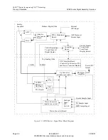
Figure 4-1 is a block diagram which shows a transmitter with an APEX exciter. This
diagram shows the ASI transport stream input to the exciter, the exciter RF output signal
connected to the transmitter IPA input, and the various required RF feedback signals from
the transmitter system to the exciter. These feedback signals are needed to perform the
linear and non-linear RTAC precorrection of exciter RF output signal.
The information contained in this overall system block diagram will be needed later, when
a detailed study of the APEX exciter block diagram is provided.
Additional exciter to transmitter systems interconnection information is covered in Section
2, Installation.

