APEX
™
Exciter Incorporating FLO
™
Technologyr
APEX Exciter Analog Assembly Overview
Theory of Operation
26
04s40
0.fm
03/08/07
888-2604-001
Page: 4-7
WARNING: Disconnect primary power prior to servicing.
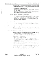
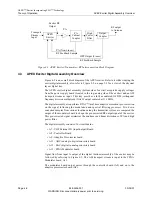
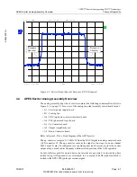
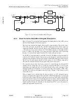
Figure 4-4 Exciter Output Spectral Response, RTAC Bypassed
4.4
APEX Exciter Analog Assembly Overview
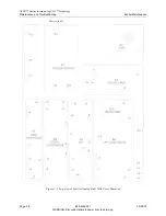
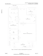
The analog assembly (top side of exciter) contains the following subassemblies. Refer to
Figure 5-1, on page 5-2 for a view of the analog (top side) assembly circuit board layout.
• A1 - Exciter power supply board
• B1 - Cooling fan.
• A6 - UDC (up/down converter interface) board
• A4 - PLL (phase lock loop) board
• A3 - Up Converter board
• A2 - Output Amplifier board
• A5 - Down Converter board.
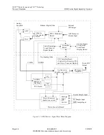
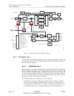
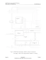
Refer to Figure 4-2 for a block diagram of the APEX exciter.
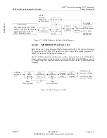
The up-converter accepts a 11.1 MHz IF from the DAC (digital to analog converter board
(A12) connector J3. The up converter converts the signal in two stages to an on channel
UHF output. It may be configured (via the front panel touch screen) to place the exciter
output at any desired center frequency within selected portions of the UHF spectrum.
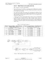
Local oscillators used for up and down conversions are generated via low noise phase
locked loops. All frequencies are referenced to a common 10 MHz standard, which is
locked to the GPS 1PPS (pulse per second) signal.
A
SWT 30 ms
*
AVG
*
1 RM
Att
25 dB
Ref
-1 dBm
Center
719 MHz
Span
10 MHz
1 MHz/
-100
-90
-80
-70
-60
-50
-40
-30
-20
-10
0
Response
Shoulder
Response
Shoulder

