Setup via HLP 4200WD Display
HRR 4104 Return Path Receiver Product Manual Rev A (3/05)
4–5
4. Press the
▲
or
▼
button until the display indicates the HRR 4104 module
you wish to set up, then press
Enter.
5. To set up Receiver A within the selected HRR 4104 module, press
▲
or
▼
until the display reads
RECEIVER A
, then press
Enter
. If you want to set up
another receiver (B, C, or D) instead, press
▲
or
▼
until the display shows
the receiver you wish to set up, then press
Enter
.
6. Press
▼
until the display reads
RECEIVER A ADJUST
, then press
Enter.
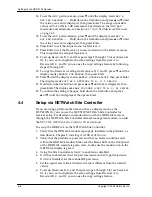
7. To set the optical alarm limit, press
▼
until the display reads
REC A OPT
ALR LIMIT ...
Hold down the
Set
button and press
▲
or
▼
until the
value you want is displayed, then press
Enter
. The range of possible values
is –18 to 0 dB, in 1 dB increments. For details on the optical alarm limit
feature, see Section
NOTE:
If you do not want to change a setting, press
Esc
before pressing
Enter
. When you change a value, until you press
Enter
, an asterisk (*)
appears next to the value to indicate that the value has been changed
but not saved.
8. To set the wavelength, press
▼
until the display reads
REC A INPUT WAV
(1550/1310NM) ...
Hold down the
Set
button and press
▲
or
▼
until
the value you want—
1550
or
1310
—is displayed, then press
Enter
.
For details on the wavelength feature, see Section
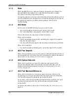
9. To set the mute to forced or unforced, press
▼
until the display reads
RECEIVER A MUTE ...
Hold down the
Set
button and press
▲
or
▼
until
the value you want—
FORCED
or
UNFORCED
—is displayed, then press
Enter
.
For details on the mute feature, see Section
10. To enable or disable AGC mode, press
▼
until the display reads
RECEIVER
A AGC MODE ...
Hold down the
Set
button and press
▲
or
▼
until the
value you want—
ENABLED
or
DISABLED
—is displayed, then press
Enter
.
For details on the AGC mode feature, see Section
4-2.
- If AGC is enabled, skip to Step 12.
- If AGC is disabled, follow Step 11, then skip to Step 16.
11. If AGC is disabled, to set the manual RF pad, press
▼
until the display
reads
REC A MAN RF PAD VALUE ...
Hold down the
Set
button and press
▲
or
▼
until the value you want is displayed, then press
Enter
. The range
of possible values is 0 to 30 dB, in 1 dB increments. Set the manual RF pad
to the value that generates the desired RF output. For details on the
manual RF pad feature, see Section
12. If AGC is enabled, to set the AGC pad setpoint, press
▼
until the display
reads
REC A AGC PAD SETPOINT ...
Hold down the
Set
button and
press
▲
or
▼
until the value you want is displayed, then press
Enter
. The
range of possible values is 0 to 30 dB, in 1 dB increments. For details on the
AGC pad setpoint feature, see Section
13. To set the AGC optical setpoint, press
▼
until the display reads
REC A
AGC OPTICAL SET ...
Hold down the
Set
button and press
▲
or
▼
until
the value you want is displayed, then press
Enter
. For details on the AGC
optical setpoint feature, see Section
Содержание HRR 4104
Страница 1: ...HRR 4104 Return Path Receiver Product Manual Manual Part No 700 0051981 Rev A March 2005...
Страница 8: ...Overview 1 4 Copyright 2005 Harmonic Inc...
Страница 18: ...User Interface Options 3 2 Copyright 2005 Harmonic Inc Figure 3 1 HLP 4200WD Platform Main menu display...
Страница 36: ...Maintenance and Troubleshooting 5 6 Copyright 2005 Harmonic Inc...
Страница 40: ...Technical Specifications A 4 Copyright 2005 Harmonic Inc...
Страница 42: ...Harmonic Inc Offices B 2 Copyright 2005 Harmonic Inc...


