Installing the HRR 4104 Receiver
2–2
Copyright © 2005 Harmonic Inc.
The following optional accessories are not included:
•
Four 4 dB couplers—to combine the RF outputs from two HRR 4104
modules in a redundant configuration
•
HFM 4000 Fiber Management Tray (see Section 2.6)
•
Four #10 screws with 10-24 UNC thread, and Phillips screwdriver—
to mount the HFM 4000 in the rack
2.3
Installing the HRR 4104
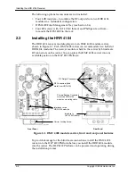
The HRR 4104 receiver module plugs into an HMC 4008 module carrier,
shown in Figure 2-1. Each HMC 4008 carrier can accommodate two half-slot
HRR 4104 modules. The receiver module is held in the carrier by blind mate
RF connectors on the carrier. You can place the HMC 4008 carrier into any
available position in the HLP 4200 Platform.
Figure 2-1. HMC 4008 module carrier, front and rear panel features
To provide leverage for the blind mate connections, install the HMC 4008
carrier into the HLP 4200 Platform before you install the HRR 4104 module
into the carrier. The HLP 4200 Platform can be powered and operating during
the installation process.
Carrier Locking Screw
Interfaces to two
HRR 4104 modules
RF Output Connectors
RF Connectors (blind
mate) from HRR 4104
Interface to
HLP 4200 Platform
Primary/Backup Connectors
to join two HRR 4104
modules via muting cable
Front Panel
Rear Panel
Содержание HRR 4104
Страница 1: ...HRR 4104 Return Path Receiver Product Manual Manual Part No 700 0051981 Rev A March 2005...
Страница 8: ...Overview 1 4 Copyright 2005 Harmonic Inc...
Страница 18: ...User Interface Options 3 2 Copyright 2005 Harmonic Inc Figure 3 1 HLP 4200WD Platform Main menu display...
Страница 36: ...Maintenance and Troubleshooting 5 6 Copyright 2005 Harmonic Inc...
Страница 40: ...Technical Specifications A 4 Copyright 2005 Harmonic Inc...
Страница 42: ...Harmonic Inc Offices B 2 Copyright 2005 Harmonic Inc...

