


Re-Tighten the
2 bolts and nuts.
Re-Tighten the
2 bolts and nuts.
Replace
Shaft Collar
Higher or lower arm
settings can be achieved
by removing top shaft
collar, retracting
T-handle, and re-inserting
arm from above or below.
Replace
Shaft Collar
Higher or lower arm
settings can be achieved
by removing top shaft
collar, retracting
T-handle, and re-inserting
arm from above or below.
34
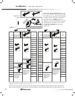
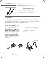
Section 2 : inStaller
Lift Adjustments
aL560 & aL580 SerIeS
hoLD-DoWN arm aDJUStmeNt
1. Drive chair onto platform after cradles have been adjusted.
(See prior page.)
[Figure 34-1]
2. Raise platform to top of travel until you hear the clutch.
[Figure 34-2]
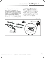
3. Loosen the two bolts and nuts in back of the vertical tube.
[Figure 34-3 and 34-4]
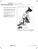
Allow arm assembly to lower until the
arm contacts the seat.
4. Lower the platform approximately 2” to 3.” Allow arm to
drop with seat. Re-tighten the two bolts and nuts.
[Figure 34-5]
5 Run lift up until top of travel, when you hear the clutch.
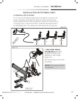
caUtIoN!
Verify that the hold-down arm produces
enough pressure on the seat to hold the
power chair firmly to the platform. The
seat should be somewhat indented by
the arm.
[Figure 34-7]
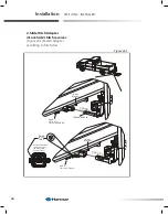
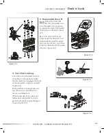
Note:
Higher or lower arm settings can be
achieved by removing top shaft collar, retracting
T-handle, and re-inserting arm from above or
below.
[Figure 34-6]
This method allows the T-handle to remain on the
same side as the key and toggle switches
OR
Entire assembly can be flipped IF desired for
opposite T-handle location.
Figure 34-1
Figure 34-2
Figure 34-3
Figure 34-4
Figure 34-5
Figure 34-6
Figure 34-7
Содержание AL010/050
Страница 62: ...900 62 Notes ...