background image

Read and understand this manual thoroughly before 

attempting to install or operate the lift. If you have any 

questions, please contact your Authorized Harmar Dealer or 

Harmar’s Technical Service Department.

Dealer Name & Contact Information:  

Serial # of Your Lift:

outside Lifts

Installation & Owner’s Manual

www.harmar.com  |  800-833-0478

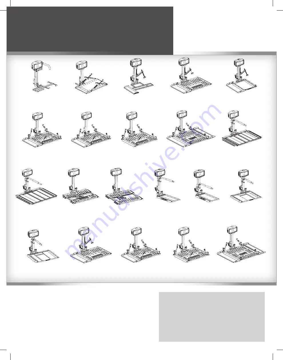
aL030 Power tote Folding 

manual Wheelchair Lift

Capacity: 100 lbs

aL010/050 micro  

Power chair / Scooter Lift

Capacity: 135 lbs

aL015 micro Scooter Lift

Capacity: 100 lbs

aL100 Universal Lift

Capacity: 350 lbs

aL160 Low Profile  

Universal Scooter Lift

Capacity: 350 lbs

aL300 Universal  

Scooter/Power chair Lift

Capacity: 350 lbs

aL300rV rV Lift

Scooter/Power chair Lift

Capacity: 350 lbs

aL500  

Universal Power chair Lift

Capacity: 350 lbs

aL301XL extra Wide 

Universal Power chair Lift

Capacity: 350 lbs

aL560 auto hold Down

Power chair Lift

Capacity: 350 lbs

aL560XL automatic 

extra Large Power  

chair Lift

Capacity: 350 lbs

aL570 auto

Power chair Lift

Capacity: 350 lbs

aL570 extra Large  

Power chair Lift

Capacity: 350 lbs

aL580 Power chair Lift

Capacity: 350 lbs

aL580XL extra Large 

Power chair Lift

Capacity: 350 lbs

aL585-SeL  

Power chair Lift

Capacity: 250 lbs

aL585-SS  

Power chair Lift

Capacity: 250 lbs

aL100hD heavy Duty 

Scooter Lift

Capacity: 400lbs

aL300hD heavy Duty Scooter/ 

Power chair Lift

Capacity: 400 lbs

aL500hD heavy Duty  

Power chair Lift

Capacity: 400 lbs

aL301XLhD extra Wide 

heavy Duty Power chair Lift

Capacity: 400 lbs

Содержание AL010/050

Страница 1: ...air Lift Capacity 350 lbs AL300RV RV Lift Scooter Power Chair Lift Capacity 350 lbs AL500 Universal Power Chair Lift Capacity 350 lbs AL301XL Extra Wide Universal Power Chair Lift Capacity 350 lbs AL560 Auto Hold Down Power Chair Lift Capacity 350 lbs AL560XL Automatic Extra Large Power Chair Lift Capacity 350 lbs AL570 Auto Power Chair Lift Capacity 350 lbs AL570 Extra Large Power Chair Lift Capa...

Страница 2: ...wing Away 24 AL030 Power Tote Ball Mount 26 CHAIR PREPARATION 27 Anchor Plate 27 U Bolt Kit 28 LIFT ADJUSTMENTS AL015 AL100 AL100HD AL160 29 AL010 050 and AL030 31 AL560 AL560XL 32 AL560 AL580 Hold Down Arm 33 AL570 AL570XL Chair Plow 34 Dock N Lock AL570 AL570 XL 35 TROUBLESHOOTING 37 EXPLODED VIEWS AL030 39 AL010 050 40 AL015 41 AL100 42 AL160 43 AL300 44 AL300RV 45 AL301XL 46 AL500 47 AL560 48 ...

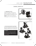
Страница 3: ... lower to the point where the vehicle begins to rise This will damage the lift IMPORTANT Positioning the chair properly on the platform is critical to ensure it is properly locked onto the lift Always verify wheels are captured by cradles or bars Please consult your dealer on the specifics of your application Figure 3 1 Figure 3 2 2 Drive Chair onto Platform Drive slowly stopping when the drive wh...

Страница 4: ...UP toggle switch in order to avoid having to bend over while you attach straps or flip the chair s armrest out of the way of the hold down arm Figure 4 1 x2 x2 Figure 4 1 Figure 4 2 4 Raising the Lift When the chair is secure use the UP toggle switch to continue raising the lift Stop when it reaches the top of travel when you hear the clutch sound Twist the key to remove Figure 4 2 ...

Страница 5: ... position This may damage the lift Drive slowly over rough terrain such as pot holes unpaved roads railroad tracks Excessive loads from rough driving will damage your lift and is not covered by the warranty If you notice any damage stop using the lift immediately Do not attempt to transport a chair or scooter with a compromised lift Damage to your chair lift vehicle may occur Take the lift to your...

Страница 6: ...g mechanism consists of a pin and keeper plate which must be disengaged before unfolding Simply hold the platform firmly and lower it approximately 2 to allow the platform to disengage and unfold Figure 6 1 WARNING Hold platform firmly while lowering the lift to its down position To lock in the upright position lift platform up before the pin engages the keeper plate Figure 6 2 WARNING Hold platfo...

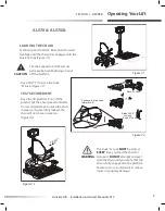
Страница 7: ... engages with the Dock N Lock Figure 7 1 CAUTION Set chair speed to SLOW and use extra caution while driving on and off the platform Raise lift 2 3 to close the Dock N Lock Figure 7 2 Test Securement Raise the lift platform 3 6 off the ground Set the chair speed controller to slow and attempt to move the chair in reverse If successfully locked the chair will not move in reverse Figure 7 3 WARNING ...

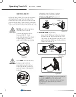
Страница 8: ...e 8 1 WARNING NEVER open the Swing Away with the chair on the lift You will damage the Swing Away and the lift It will potentially damage the vehicle and the chair Any of these actions will VOID your warranty Figure 8 4 Remove Safety Pin Pull T Handle AL105 AL105L Remove Safety Pin Pull T Handle AL105 AL105L Figure 8 3 Figure 8 5 Opening the Swing Away 1 Remove Safety Pin Figure 8 3 2 Pull T Handl...

Страница 9: ...sing the Swing Away Close the Swing Away unit as you would a car door WARNING Stay clear of the latching mechanism Figure 9 1 Figure 9 4 SAFELY CLOSED WRONG SAFELY CLOSED WRONG Figure 9 2 Figure 9 3 WARNING Always install the safety pin CAUTION Verify that the T handle has fully retracted ...

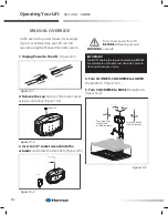
Страница 10: ... to use the Manual Override Failure to do so result in serious injury WARNING Disconnect power from lift BEFORE attempting manual override 1 Unplug Power to the Lift Figure 10 1 2 Remove the cap on top of the motor cover using a coin or key Figure 10 2 3 Insert a 3 8 socket wrench into the actuator and rotate the Hex Shaft Figure 10 3 Figure 10 4 In the event of a power failure for example if your...

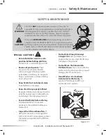
Страница 11: ...contact the dealer you purchased the lift from for repairs Do Not Enter Steep Driveways Straight On Enter and leave at an angle to the street so that the lift does not drag on the ground Do Not Move the Vehicle with Platform Down If you move with the platform in the down position you will damage the lift mechanism Hand Wash or Use Touchless Automatic Car Wash only To prevent lift damage do NOT use...

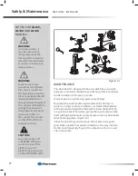
Страница 12: ...EVERSE When the scooter is clear of the platform raise the platform by pushing up on the UP DOWN switch MAINTENANCE This Outside Lift is designed to be as trouble free as possible however some basic maintenance will ensure that it continues to offer reliable use for years to come Oil pivot points on all moving parts every 30 days Re grease the inside vertical square tube every 30 days in winter or...

Страница 13: ...nt at 800 378 6648 or tech harmar com If you do not understand any portion of installation or operation please consult our technical service department or authorized mobility dealer Do not attempt to install or use this NOTE The following section is designed for the professional installer We strongly recommend that a certified dealer install the lift configure the docking device and instruct the u...

Страница 14: ... box contents Review each part against the packaging checklist to ensure that all parts have been included If any parts are missing or damaged immediately contact the dealer who sold the lift Do not attempt to install or use a lift that has missing or damaged parts ...

Страница 15: ...rness first will ensure you have power to the lift during installation This allows the motor to do the lifting for you If you skip this step use a shop battery 2 Position the open box behind the vehicle Slice the corner seams Figure 15 1 3 Determine Install Hitch Height Adapter Measure the hitch to ground distance so you can save time by selecting components that fit between lift and vehicle so as...

Страница 16: ...Section 2 Installer Preparation 4 Connect power to the lift Figure 16 1 Insert and turn key Press DOWN to extend the lift Figure 16 2 5 When extended 3 or more flip up to vertical Figure 16 3 Figure 16 1 Figure 16 3 Figure 16 2 Figure 16 4 6 Align the hitch adapter using the power of the lift The lift will slide on the cardboard box Figure 16 4 ...

Страница 17: ...lift end It goes to the trailer hitch area where the lift will mount Figure 17 1 WARNING DO NOT connect the red wire until LAST 2 Begin routing the wiring harness at the vehicle battery Attach the black wire to the negative terminal on the battery Do NOT attach the red wire until the very end of installation Figure 17 2 CAUTION NEVER attempt to connect the harness to a secondary power source Alway...

Страница 18: ...r seals are inside back of connector and close the hinged retainer 7 Plug connector into the lift 8 LAST attach red wire to the positive terminal on the battery Figure 18 3 If the harness is too long coil the excess wire and secure it to the vehicle frame bumper with the supplied wire ties Figure 18 1 RED WIRE RED WIRE OR LAST SIDE MOUNT TOP MOUNT RED WIRE RED WIRE OR LAST SIDE MOUNT TOP MOUNT Fig...

Страница 19: ...ndard two contact trailer connector is included with the lift This is for the license plate lamp If your vehicle is not equipped with the proper connector you can use the BROWN WIRE to make a wire splice and achieve the same result Figure 19 3 TECH NOTE MOTOR TESTING Troubleshooting with a test light or voltage meter may give a false indication When you probe for 12 volts the reading may indicate ...

Страница 20: ...is reputable insured and capable Their work reflects directly on the customer s perception of your mobility lift installation 1 Calculate the weights of the lift mobility device and where applicable the Swing Away option Be certain that the total weight does not exceed the hitch s recommended tongue weight A range of hitches are available capable of bearing different amounts of weight The lift man...

Страница 21: ...C Please contact Harmar s Technical Service Dept IF H128 Class2Short H124 Class 3 Short X For shallow hitches ex Spare Tire blocked hitches a short Hitch Adapter may be required SOME AL126 Standard Class 2 AL123 Standard Class 3 X 0 7 5 X 7 5 10 X 10 13 5 AL127 Class 2 Extra long AL125 Class 3 Extra long AL125 Class 3 Extra long 3 S S A L C 2 S S A L C Please contact Harmar s Technical Service Dep...

Страница 22: ...TERS PLEASE CONTACT TECHNICAL SERVICE DEPARTMENT FOR AVAILABILITY OF LARGER DROP ADAPTERS STANDARD MOUNT AL107 HITCH POST NO SWING AWAY STANDARD MOUNT AL107 HITCH POST NO SWING AWAY SWING AWAY OPTIONAL SWING AWAY OPTIONAL 22 Section 2 Installer Installation HITCH ADAPTERS Con t The effective range of the Hitch Adapter changes slightly if the lift is equipped with the standard AL107 Hitch Post Figu...

Страница 23: ...Adapter against receiver wall eliminating rattles and lift movement HHCS 1 2 13 x 3 FULLY THREADED Outside Lifts Installation Owner s Manual 2013 23 Section 2 Installer Installation Optimizing Hitch Height Figure 23 1 Figure 23 2 INSTALLATION WITH HITCH POST You can vary the lift height by changing the Hitch Adapter s orientation and location This helps you optimize the vehicle s ground clearance ...

Страница 24: ... 3 1 2 x3 OR 24 Section 2 Installer Installation Installing the Hitch Adapter 1 Attach hitch adapter to hitch post orientated properly according to the application s Hitch Height Figure 24 1 2 Attach Hitch Post to lift Do NOT over tighten 3 Slide Hitch Adapter into vehicle s hitch receiver Fasten Adapter according to hitch class Figure 23 2 Figure 24 1 ...

Страница 25: ...Hitch Height You can vary the lift height by changing the Hitch Adapter s orientation and location This helps you optimize the vehicle s ground clearance to ensure that the platform lays flat on the ground when it reaches the end of its travel Consult Figure 25 1 to select the orientation needed for the vehicle based on the Hitch Height that is the vehicle s hitch receiver distance to the ground 1...

Страница 26: ...yloc Nut CLASS 2 CLASS 3 PINCH BOLT TUBE HHCS 1 2 13 x 3 1 2 or 4 Presses Hitch Adapter against receiver wall eliminating rattles and lift movement 1 2 Hex Nyloc Nut HHCS 1 2 13 x 3 FULLY THREADED THREADED HOLE 1 2 Hex Nyloc Nut CLASS 2 CLASS 3 26 Section 2 Installer Installation Figure 26 1 2 Slide Hitch Adapter into vehicle s hitch receiver Figure 26 1 Fasten Adapter according to hitch class ...

Страница 27: ... Away OR CLASS 3 CLASS 2 Swing Away OR CLASS 3 CLASS 2 Outside Lifts Installation Owner s Manual 2013 27 Section 2 Installer Installation AL030 POWER TOTE INSTALLATION WITH BALL MOUNT HITCH ADAPTER Figure 27 1 Figure 27 2 Ball Mount Hitch Adapter and stabilizer Standard equipment shipped with AL030 Power Tote AL030 can also be upgraded with Class 3 and Class 2 hitch adapters 1 Install bumper mount...

Страница 28: ...tend about 1 1 2 out from the side of the cushion The user can attach the strap hooks to the Anchor Plate in order to secure the chair to the lift Figure 28 1 Figure 28 2 Installing the Anchor Plate 1 Remove the seat from the chair 2 Loosen the screws that attach the plate of the bottom of the seat Allow enough room to slide the Anchor Plate between the seat and the seat plate 3 Attach the Anchor ...

Страница 29: ...n each side to the frame as shown Figure 29 1 Ensure that the loop extends to the outside of the chair so the user can attach the strap hooks Figure 29 1 Each chair is slightly different so the U bolt placement will differ among models and manufacturers Place the U bolts towards the center of the seat if possible Due to different seat types you may be forced to install the U bolts more towards the...

Страница 30: ...ter The scooter can fall off the lift if not properly secured Be sure to instruct the end user to avoid entering steep driveways straight on Enter and leave at an angle to the street so that the lift platform does not drag on the ground CAUTION Drive the scooter off in REVERSE When the scooter is clear of the platform raise the platform by pushing up on the UP DOWN switch Setting Hold Down Foot He...

Страница 31: ...l 2013 31 Section 2 Installer Lift Adjustments AL015 AL100 AL100HD AL160 LIFT ADJUSTMENTS Con t 7 Tighten the jam nut to lock it in place when the foot is positioned properly When the lift is properly adjusted lower the platform to the ground and raise it back to the transporting position Repeat this several times to ensure all parts operate properly and that the scooter is well secured Next remov...

Страница 32: ...d down arm To adjust tighten or loosen the bolt and nut located at the pivot point Figure 32 1 Adjusting the AL030 Hold Down Arm The AL30 s hold down arm height requires adjustment to properly clamp a specific wheelchair to the platform 1 Position the folded wheelchair on the platform being certain the large rear wheels fall into the cradles of the platform 2 Loosen the two bolts and nuts located ...

Страница 33: ...justment ALL AL560 platform components are loose You MUST tighten these screws and nuts before use Figure 33 1 1 Estimate the chair s center position depending on driver s side or passenger s side entry preference Locate the drive wheel s position Figure 33 2 Adjust the two main cradle positions to match Capture smaller wheels on the two larger skins 2 Drive chair onto platform Verify chair is sec...

Страница 34: ... of the vertical tube Figure 34 3 and 34 4 Allow arm assembly to lower until the arm contacts the seat 4 Lower the platform approximately 2 to 3 Allow arm to drop with seat Re tighten the two bolts and nuts Figure 34 5 5 Run lift up until top of travel when you hear the clutch CAUTION Verify that the hold down arm produces enough pressure on the seat to hold the power chair firmly to the platform ...

Страница 35: ...1 to ensure the chair will be compatible with the Dock N Lock system Read understand and follow the instructions provided with your specific plow We highly recommend installing the Plow under the chair prior to adjusting the heights of the Dock N Lock on the platform Figure 35 2 This ensures the guidelines on the next page are accurate If you need additional holes to install the plow be sure to re...

Страница 36: ... The AL570 and AL570XL are shipped from the factory with the Dock N Lock system attached directly to the platform Subtract 1 1 4 from the measurement taken to the right and use the appropriate number and combinations of spacers to raise to Dock and Lock to match the chair Figure 36 1 Example For AL570 if the chair s pin to ground measurement is 2 00 then subtract 1 1 4 To prepare the need for a to...

Страница 37: ...ugh the upper nylon portion of nut but not so long that the bolts interfere with the plow Figure 37 2 4 Test Chair Locking Drive chair onto the platform Test its locking on the platform Verify that the plow s pin engages the Dock and Lock system Adjust as needed Figure 37 3 Raise platform to engage lock and test the chair to ensure that it is secure in all directions If Dock and Lock station does ...

Страница 38: ...isolate sections of the lift wiring using process of elimination with a known good fully charged 12V automotive battery or known good fully charged power chair scooter battery Problem Lift does not operate Lift operates slowly or intermittently Cause Bad electrical connection s Circuit breaker Solution Check clean all connections that might be loose or dirty The lift motor requires quality electri...

Страница 39: ...f the vehicle Any higher vehicles will require a different hitch adapter See Hitch Adapter section of this manual Problem Extra length of wire leads to the lift motor Cause Wire was provided for optional Swing Away Solution The extra wire is provided in case a Swing Away option is used with the lift If a Swing Away is not installed coil the extra wire and zip tie it to the frame out of the way of ...

Страница 40: ... H H 1 5 1 P Z 0 5 0 x 8 2 4 1 D A E H X E H Z 0 5 _ 0 8 2 5 2 _ 0 S C H H 1 6 1 P Z 5 2 3 x 8 1 5 1 5 D A E H X E H Z 5 2 _ 3 8 1 1 3 _ 0 S C H H 1 7 1 P Z 0 0 5 x 6 1 8 3 D A E H X E H Z 0 0 _ 5 6 1 7 3 _ 0 S C H H 2 8 1 T L P C N I Z 5 2 2 X 3 1 2 1 D A E H X E H Z 5 2 _ 2 3 1 0 5 _ 0 S C H H 1 9 1 P Z 0 5 3 x 3 1 2 1 D A E H X E H Z 0 5 _ 3 3 1 0 5 _ 0 S C H H 1 0 2 P Z 5 7 0 L L I R D F L E S...

Страница 41: ...0 HARDWARE PACK 9 1 ALA580 U BOLT HARDWARE KIT 10 1 ALA58040C ANCHOR PLATE 11 1 ALA99995 LABEL SERIAL NUMBER 12 1 H00 1A03 A HARDWARE PACK 13 1 200 2A01 A MOTOR COVER ASSEMBLY 14 1 HHCS 0_25 20 0_75 NP Z HEX HEAD 1 4 20 x 0 75 ZP 15 4 HWTS 14 0_75 Z HEX WASHER 14 SELF DRILL 0 75 ZP 4 1 1 1 6 1 7 1 8 1 9 1 11 1 14 1 3 1 2 1 15 4 10 1 12 1 13 1 5 1 EXPLODED VIEW AL010 050 27 Outside Lifts Installati...

Страница 42: ...4 1 H14045 CLEVIS PIN 25 1 HHCS 0_25 20 0_75 NP Z HEX HEAD 1 4 20 x 0 75 ZP 26 3 HHCS 0_25 20 1_75 Z HEX HEAD 1 4 20 x 1 75 ZP 27 2 HHCS 0_50 13 2_50 Z HEX HEAD 1 2 13 x 2 50 ZP 28 4 HWTS 14 0_75 Z HEX WASHER 14 SELF DRILL 0 75 ZP 29 3 NUT 0_25 20 NYLOCK Z NUT NYLOCK 1 4 20 ZP 30 3 NUT 0_50 13 NYLOCK Z NUT NYLOCK 1 2 13 ZP 31 2 NUT 0_62 11 JAM Z NUT JAM 5 8 11 ZP 32 1 PIN 0_12 1_50 CO SS COTTER PI...

Страница 43: ...50 CO SS NUT 0_50 13 NYLOCK Z NUT 0_50 13 NYLOCK NTE Z NUT 0_37 16 NYLOCK NTE Z NUT 0_25 20 NYLOCK Z HHCS 0_50 13 2_50 Z HHCS 0_50 13 0_75 Z HHCS 0_25 20 1_75 Z HHCS 0_25 20 0_75 NP Z PIN 0_18 1_50 RP Z 1 43 2 4 5 10 1 1 2 9 1 52 51 50 49 48 47 45 46 44 SHSB 0_62 2_50 Z RR 0_62 EC Z RIV 188 SS 1 2 2 3 2 6 3 4 2 2 3 1 1 36 42 41 40 39 38 37 34 35 33 32 31 30 NUT 10 24 NYLOCK Z NUT 0_62 11 JAM Z HWT...

Страница 44: ...EAD 1 4 20 x 0 75 ZP 32 3 HHCS 0_25 20 1_75 Z HEX HEAD 1 4 20 x 1 75 ZP 33 2 HHCS 0_50 13 0_75 Z HEX HEAD 1 2 13 x 0 75 ZP 34 2 HHCS 0_50 13 2_50 Z HEX HEAD 1 2 13 x 2 50 ZP 35 4 HWTS 14 0_75 Z HEX WASHER 14 SELF DRILL 0 75 ZP 36 3 NUT 0_25 20 NYLOCK Z NUT NYLOCK 1 4 20 ZP 37 6 NUT 0_37 16 NYLOCK NTE Z NYLOCK NUT THIN 3 8 16 ZP 38 2 NUT 0_50 13 NYLOCK NTE Z THIN NUT NYLOCK 1 2 13 ZP 39 3 NUT 0_50 ...

Страница 45: ...Z NUT 0_50 13 NYLOCK NTE Z NUT 0_37 16 NYLOCK NTE Z NUT 0_25 20 NYLOCK Z HHCS 0_50 13 2_50 Z HHCS 0_50 13 0_87 Z HHCS 0_50 13 0_75 Z HHCS 0_25 20 1_75 Z HHCS 0_25 20 0_75 NP Z 2 37 4 5 2 2 9 2 46 45 41 44 43 42 39 40 38 RR 0_62 EC Z 1 1 1 RIV 188 SS 4 6 4 2 2 2 2 2 30 36 35 34 32 33 31 28 29 27 26 25 24 HWTS 14 0_75 Z 1 1 1 1 1 H50011B H50010B H14407 H14045 NUT NYLOCK 1 2 13 ZP WASHER FLAT 1 2 NYL...

Страница 46: ...Z HHCS 0_25 20 0_75 NP Z 37 36 2 5 1 33 35 34 9 1 32 31 2 2 WASH 0_50 1_50 0_12 N RIV 188 SS PIN 0_50 3_00 CL Z PIN 0_12 1_50 CO SS NUT 10 24 NYLOCK Z NUT 0_50 13 NYLOCK Z 29 30 28 6 4 4 26 27 25 2 2 2 2 22 24 23 1 2 21 20 1 1 HHTS 12 14 0_75 Z HHCS 0_50 13 2_50 Z HHCS 0_50 13 0_87 Z HHCS 0_50 13 0_75 Z H50010B H50011B H14407 200 2A01 A THIN NUT NYLOCK 1 2 13 ZP WASHER FLAT 1 2 NYLON WASHER FLAT 1...

Страница 47: ... 4 20 x 0 75 ZP 30 1 HHCS 0_25 20 1_75 Z HEX HEAD 1 4 20 x 1 75 ZP 31 4 HHCS 0_50 13 0_75 Z HEX HEAD 1 2 13 x 0 75 ZP 32 2 HHCS 0_50 13 2_50 Z HEX HEAD 1 2 13 x 2 50 ZP 33 4 HWTS 14 0_75 Z HEX WASHER 14 SELF DRILL 0 75 ZP 34 1 NUT 0_25 20 NYLOCK Z NUT NYLOCK 1 4 20 ZP 35 12 NUT 0_37 16 NYLOCK NTE Z THIN NUT NYLOCK 3 8 16 ZP 36 4 NUT 0_50 13 NYLOCK NTE Z THIN NUT NYLOCK 1 2 13 ZP 37 2 NUT 0_50 13 N...

Страница 48: ...25 0_50 0_31 N PIN 0_50 3_00 CL Z PIN 0_12 1_50 CO SS NUT 0_50 13 NYLOCK Z NUT 0_50 13 NYLOCK NTE Z NUT 0_25 20 NYLOCK Z HHCS 0_50 13 2_50 Z HHCS 0_50 13 0_75 Z HHCS 0_25 20 1_75 Z HHCS 0_25 20 0_75 NP Z 2 32 4 5 2 2 9 2 41 40 39 38 37 36 1 34 35 33 1 1 RR 0_62 EC Z NUT 10 24 NYLOCK Z RIV 188 SS 4 4 2 4 2 2 1 25 31 30 29 1 27 28 26 1 23 24 22 1 HWTS 14 0_75 Z H50011B H50010B H14407 NUT NYLOCK 1 2 ...

Страница 49: ...SSEMBLY PARTS ITEM QTY N O I T P I R C S E D O N T R A P WASH 0 50 1 50 0 12 N WASH 0 50 1 06 0 0 RH SS WASH 0 25 0 62 0 04 RH SS SPCR 0 25 0 50 0 31 N SHCS 0 25 20 3 25 Z PIN 0 50 3 00 CL Z PIN 0 12 1 50 CO SS NUT 0 50 13 NYLOCK Z NUT 0 25 20 NYLOCK Z 32 30 31 29 4 2 5 1 27 28 26 24 25 23 1 2 1 3 2 4 HWTS 14 0 75 Z WASHER FLAT 1 2 NYLON WASHER FLAT 1 2 SS WASHER FLAT 1 4 SS SPACER 1 4 for CAM SPR...

Страница 50: ... 0 1 0 1 1 H 1 6 1 ASSEMBLY PARTS ITEM QTY N O I T P I R C S E D O N T R A P WASH 0 50 1 50 0 12 N WASH 0 50 1 06 0 80 RH SS WASH 0 25 0 62 0 04 RH SS SPCR 0 25 0 50 0 31 N SHCS 0 25 20 3 25 Z PIN 0 50 3 00 CL Z PIN 0 12 1 50 CO SS NUT 0 50 13 NYLOCK Z NUT 0 25 20 NYLOCK Z 32 30 31 29 4 2 5 1 27 28 26 24 25 23 1 2 1 3 2 4 HWTS 14 0 75 Z WASHER FLAT 1 2 NYLON WASHER FLAT 1 2 SS WASHER FLAT 1 4 SS S...

Страница 51: ... 0 0 2 5 2 0 S C H H 1 0 2 P Z 5 7 1 X 0 2 4 1 D A E H X E H Z 5 7 1 0 2 5 2 0 S C H H 1 1 2 P Z 5 2 1 X 6 1 8 3 D A E H X E H Z 5 2 1 6 1 7 3 0 S C H H 4 2 2 P Z 0 5 2 X 3 1 2 1 D A E H X E H Z 0 5 2 3 1 0 5 0 S C H H 2 3 2 P Z L 4 3 L L I R D F L E S 4 1 R E H S A W X E H Z 5 7 0 4 1 S T W H 4 4 2 P Z 0 2 4 1 K C O L Y N T U N Z K C O L Y N 0 2 5 2 0 T U N 1 5 2 P Z 6 1 X 8 3 K C O L Y N T U N Z...

Страница 52: ... H Z P N 5 7 0 0 2 5 2 0 S C H H 1 1 2 P Z 5 7 0 0 X 2 4 1 D A E H X E H Z 5 7 0 0 2 5 2 0 S C H H 4 2 2 P Z L 5 7 1 0 X 2 4 1 D A E H X E H Z 5 7 1 0 2 5 2 0 S C H H 1 3 2 P Z 0 5 1 6 X 1 8 3 D A E H X E H Z 0 5 1 6 1 7 3 0 S C H H 4 4 2 P Z L 0 5 2 3 X 1 2 1 D A E H X E H Z 0 5 2 3 1 0 5 0 S C H H 2 5 2 P Z L 4 3 L L I R D F L E S 4 1 R E H S A W X E H Z 5 7 0 4 1 S T W H 4 6 2 P XZ 0 2 4 1 K C ...

Страница 53: ...S E L D N A H T 1 R 9 6 0 6 5 H 1 2 2 R E K C I T S R E T N E 1 0 1 0 7 5 H 1 3 2 P A C D N E R E T E M A I D 5 2 1 2 0 1 2 5 7 H 2 4 2 P Z 5 7 0 0 X 2 4 1 D A E H X E H Z 5 7 0 0 2 5 2 0 S C H H 1 5 2 P Z 5 7 1 0 X 2 4 1 D A E H X E H Z 5 7 1 0 2 5 2 0 S C H H 1 6 2 P Z 0 5 2 3 X 1 2 1 D A E H X E H Z 0 5 2 3 1 0 5 0 S C H H 2 7 2 P Z 5 7 0 L L I R D F L E S 4 1 R E H S A W X E H Z 5 7 0 4 1 S T ...

Страница 54: ...N I P G N I R P S E L D N A H T 1 R 9 6 0 6 5 H 1 2 2 R E K C I T S R E T N E 1 0 1 0 7 5 H 1 3 2 P A C D N E R E T E M A I D 5 2 1 2 0 1 2 5 7 H 2 4 2 P Z 5 7 0 0 X 2 4 1 D A E H X E H Z 5 7 0 0 2 5 2 0 S C H H 1 5 2 P Z 5 7 1 0 X 2 4 1 D A E H X E H Z 5 7 1 0 2 5 2 0 S C H H 1 6 2 P Z 0 5 2 3 X 1 2 1 D A E H X E H Z 0 5 2 3 1 0 5 0 S C H H 2 7 2 P Z 5 7 0 L L I R D F L E S 4 1 R E H S A W X E H ...

Страница 55: ...25 DIAMETER END CAP HEX HEAD 1 4 20 X 0 75 ZP HEX HEAD 1 4 20 X 1 75 ZP HEX HEAD 1 2 13 X 2 50 ZP HEX WASHER 14 SELF DRILL 0 75 ZP NUT NYLOC 1 4 20 ZP NUT NYLOC 1 2 13 ZP COTTER PIN CLEVIS PIN 1 2 X 3 L ZP E CLIP for 5 8 X SHAFT SHCS 1 4 20 X 3 1 4 ZP SPACER 1 4 for CAM SPRINGS WASHER FLAT 1 4 SS WASHER FLAT 1 2 SS WASHER FLAT 1 2 PLASTIC ASSEMBLY PARTS AL 585 SEL ASSEMBLY PARTS AL 585 SEL ITEM IT...

Страница 56: ... ZP COTTER PIN CLEVIS PIN 1 2 X 3 L ZP E CLIP for 5 8 X SHAFT SHCS 1 4 20 X 3 1 4 ZP SPACER 1 4 for CAM SPRINGS WASHER FLAT 1 4 SS WASHER FLAT 1 2 SS WASHER FLAT 1 2 PLASTIC 27 1 28 2 30 1 34 2 10 1 12 1 14 2 26 1 32 1 2 1 3 1 19 1 4 1 1 1 20 1 21 1 33 1 36 1 37 2 11 1 17 1 29 4 16 1 22 1 30 2 35 2 18 2 9 1 5 1 6 1 39 4 25 1 23 1 24 1 31 2 38 5 1 8 7 1 13 1 ASSEMBLY PARTS AL 585 SS ASSEMBLY PARTS ...

Страница 57: ... 3 N I P S I V E L C 5 4 0 4 1 H 1 1 3 E T A L P M U N I M U L A 7 0 4 4 1 H 1 2 3 P Z 5 7 0 0 X 2 4 1 D A E H X E H Z P N 5 7 0 0 2 5 2 0 S C H H 1 3 3 P Z 5 7 1 0 X 2 4 1 D A E H X E H Z 5 7 1 0 2 5 2 0 S C H H 3 4 3 P Z 5 7 0 3 X 1 2 1 D A E H X E H Z 5 7 0 3 1 0 5 0 S C H H 2 5 3 P Z 0 5 2 3 X 1 2 1 D A E H X E H Z 0 5 2 3 1 0 5 0 S C H H 2 6 3 P Z 5 7 0 L L I R D F L E S 4 1 R E H S A W X E H...

Страница 58: ... F E L B 0 1 0 0 5 H 2 6 2 E U L B T N A I R T S Q D N A H T H G I R B 1 1 0 0 5 H 2 7 2 P Z 5 7 0 0 X 2 4 1 D A E H X E H Z P N 5 7 0 0 2 5 2 0 S C H H 1 28 P Z 5 7 1 0 X 2 4 1 D A E H X E H Z 5 7 1 0 2 5 2 0 S C H H 1 9 2 P Z 5 7 0 3 X 1 2 1 D A E H X E H Z 5 7 0 3 1 0 5 0 S C H H 2 0 3 P Z 87 0 X 3 1 2 1 D A E H X E H 0_87 3 1 0 5 0 S C H H 2 1 3 P Z 0 5 2 3 X 1 2 1 D A E H X E H Z 0 5 2 3 1 0 ...

Страница 59: ...U L B T N A I R T S Q D N A H T H G I R B 1 1 0 0 5 H 2 28 P Z 5 7 0 0 X 2 4 1 D A E H X E H Z P N 5 7 0 0 2 5 2 0 S C H H 1 9 2 P Z 5 7 1 0 X 2 4 1 D A E H X E H Z 5 7 1 0 2 5 2 0 S C H H 1 0 3 P Z 0 5 2 3 X 1 2 1 D A E H X E H Z 0 5 2 3 1 0 5 0 S C H H 2 1 3 L E E T S P Z 5 E D A R G L 4 3 3 1 2 1 S C H H Z 5 7 0 3 1 0 5 0 S C H H 4 2 3 P Z L 4 3 L L I R D F L E S 4 1 2 1 R E H S A W X E H Z 5 7...

Страница 60: ...5 H 2 3 2 E U L B T N A I R T S Q D N A H T H G I R B 1 1 0 0 5 H 2 4 2 P Z 5 7 0 0 X 2 4 1 D A E H X E H Z P N 5 7 0 0 2 5 2 0 S C H H 1 5 2 P Z 5 7 1 0 X 2 4 1 D A E H X E H Z 5 7 1 0 2 5 2 0 S C H H 1 6 2 P Z 5 7 0 3 X 1 2 1 D A E H X E H Z 5 7 0 3 1 0 5 0 S C H H 4 7 2 P Z 0 5 2 3 X 1 2 1 D A E H X E H Z 0 5 2 3 1 0 5 0 S C H H 2 28 P Z 5 7 0 L L I R D F L E S 4 1 R E H S A W X E H Z 5 7 0 4 1...

Страница 61: ...5 P Z 3 1 2 1 K C O L Y N T U N Z K C O L Y N 3 1 0 5 0 T U N 3 6 P Z H T 0 D X O 6 0 1 D X I 2 1 T A L F R E H S A W 6 0 08 RH Z 0 1 0 5 0 H S A W 2 7 8 P Z H T 2 1 0 D X O 7 3 1 D X I 2 1 T A L F R E H S A W Z H R 2 1 0 7 3 1 0 5 0 H S A W 2 KEYSWITCH ACTUATOR 12V POLE REVERSING SWITCH BATTERY TRAILER PLUG MOTOR COVER LIGHT BR O W N CIRCUIT BREAKER VEHICLE HARNESS LIFT LIGHT TYPICAL HARDWARE PAC...

Страница 62: ...900 62 Notes ...

Страница 63: ...ed my harmar lift because of Style Appearance Harmar Representative Previous Experience Ease of Use Recommendation Price Value Friend or Acquaintance Saw Harmar product somewhere Other____________________________ Harmar Mobility warrants its lift products against defects in material mechanical and electrical components parts excluding labor cost batteries paint and covers for a period of three 3 y...

Страница 64: ...Outside Lifts Installation Owner s Manual www harmar com 800 833 0478 2075 47th Street Sarasota Florida 34234 2013 Harmar MKT OALM HARMAR 11 06 13 Part 999 3A06 AA Rev B ...

Отзывы: